

CH7_Machine Basic Operation_Fanuc Turning
today
2024-10-23
local_offer
Fanuc Turning
visibility
2679
7. Machine Basic Operation
7.1 ZRN Operation
Please do return each axis to the home position in order to establish a reference position
7.1.1 Procedure
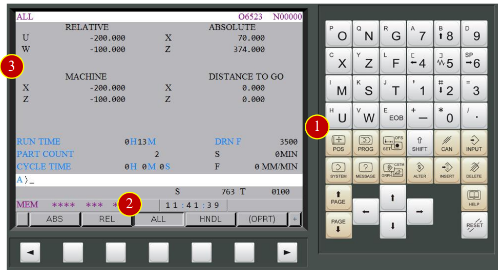
(1) Press【POS】to display the coordinate function
(2) Press【ALL】to display all of the coordinate value
(3) Check Machine Coordinates Value:
RELATIVE : The coordinate value based on the assigned position
ABSOLUTE : The coordinate value based on Workpiece coordinate zero point
MACHINE : The point that is specific to a machine reference point
DISTANCE TO GO : Shows the distance from the current tool position
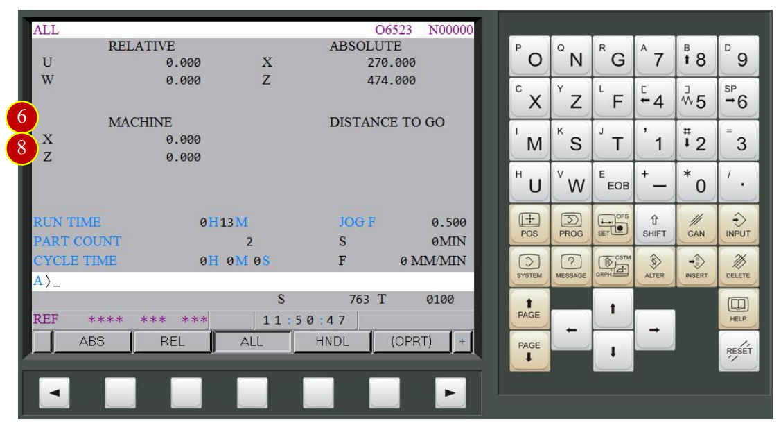
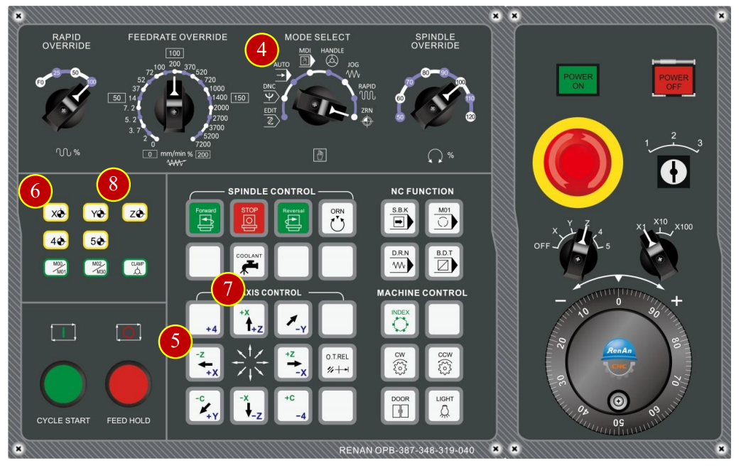
(4) Switch to【ZRN】mode (Zero Return)
(5) Press [+X], X axis starts to move toward reference point rapidly
(6) When ZRN light up means X axis has return to reference point,
and machine coordinate is 0
(7) Press [+Z], Z axis starts to move toward reference point,
(8) When ZRN light up means the Z axis has return to reference point,
and machine coordinate is 0
7.2 Work Coordinates Setting (OFFSET)
When replacing the workpiece, preset the work coordinate system (X & Z axis) according to the workpiece’s dimension.
After the installation, tool geometry offset is necessary
so that the cutting process will be executed correctly.
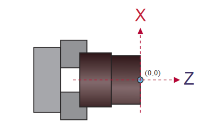
The program zero point in workpiece coordinate system usually sets in the right side
of the center of the part
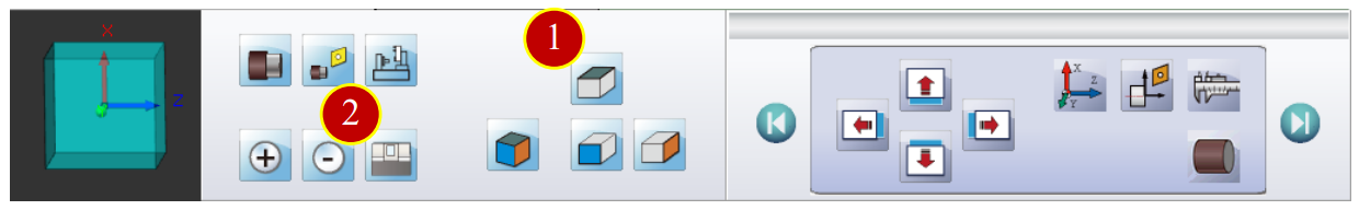
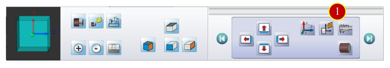
7.2.1 View Adjustment
Adjust the view to the proper angle and dimension for offsetting
(1) Press【Top View】via toolbar
(2) Press【Shell】to hide the shell of machine
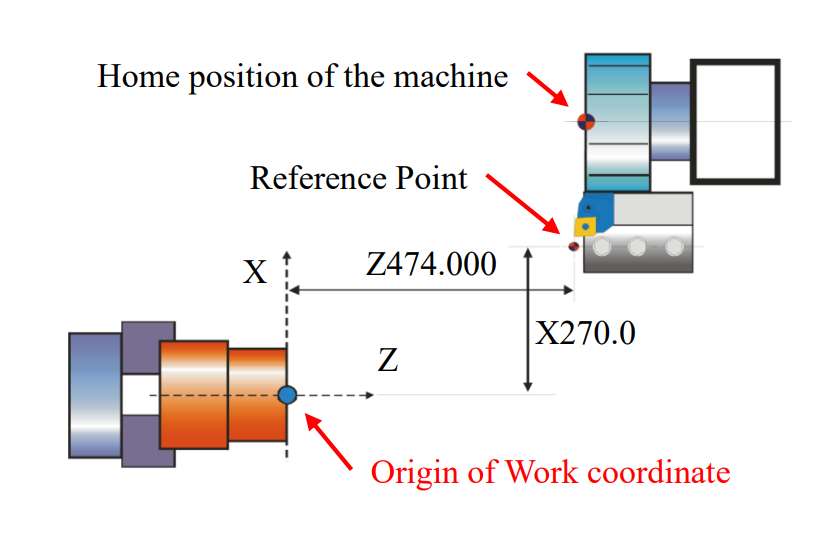
7.2.2 Work Shift Coordinate Setting (Reference Tool)
The definition of Work Shift:
(1) The shifted distance between zero point and reference position is called Work Shift Value
(2) By aligning the reference tool, the nose will be shown as a shift reference point which is the shifting reference point of turret’s tool
(3) When the turret returned to reference position, Work shift value will be indicated as an absolute coordinate of the program. Hence, machine will run the program and do all kind of cutting from this position
Reference Point Definition Example:
(1) X Axis: Make “center line of the Inner Tool Holder” as a reference position
(2) Z Axis: Make the nose of the external-rough tool as a reference position
Advantages:
(1) Set the central hole line of internal carriage as the standard point of X axis
(a) The value of the distance from the central position of internal carriage to central position of spindle is fixed. It won’t be changed by workpiece or tool. Therefore, each machine key in only one time and the X value will be permanently fixed
(b) The fixed X axis geometry value of drill, thread, milling is 0. Offset here is not necessary
(c) The X axis geometry value of internal tool is equal to the minimum diameter of external cutting which can be much easier to distinguish the offset value of X axis and assure its precision readable
(2) Set the tool nose of external tool as the reference position of Z axis
(a) In general, external tool is on the turret and is easier to cut the casting face of the material
(b) After the offset, the geometry value Z of each tool is equal to the extension value of each tool
7.2.3 Work Shift Coordinate Setting (Offset Base Plane)
It is necessary to cut a shared base plane before setting the Work shift and offset
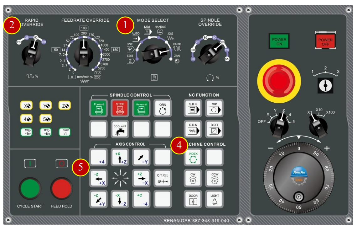
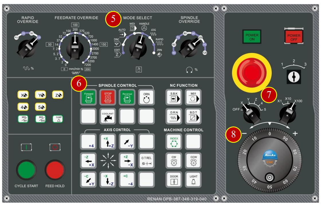
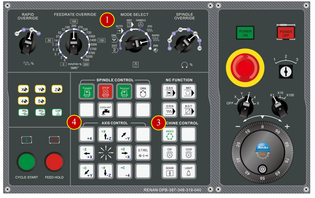
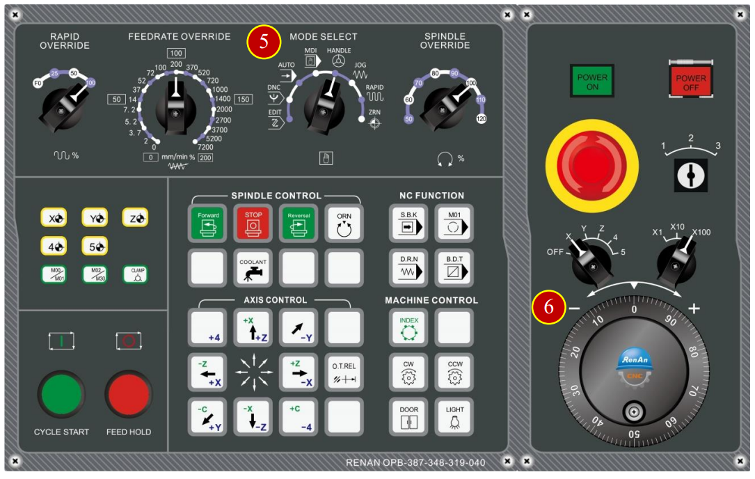
(1) Switch to【RAPID】mode
(2) Before manual operating, switch【RAPID OVERRIDE】to 50% (or 25%),
100% rapid movement is not allowed under machining execution
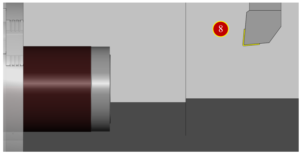
(3) Move the carriage to the Safe Tool Change position
(about 150mm left to the Workpiece)
(4) Select External Rough Tool, take No.1 tool (default) as example, change to No.1 tool
(5) Press【-X】,【-Z】to rapid traverse the tool about 50mm left to the Workpiece
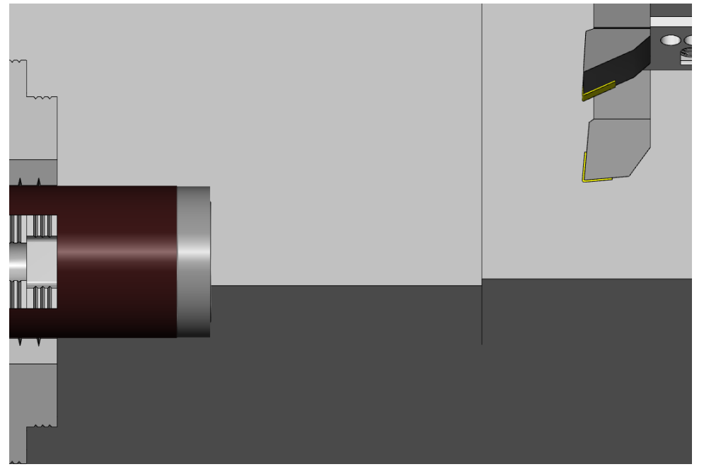
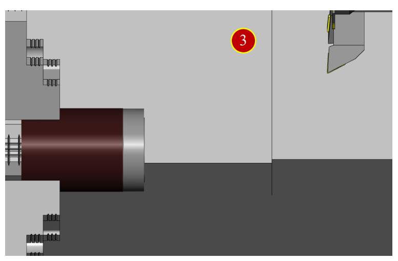
7.2.4 Cutting the Reference Face
(1) Switch to【HANDLE】mode
(2) Press【Forward】to rotate the spindle forward
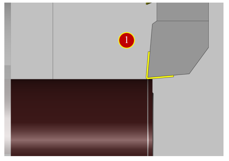
(3) Move tool to the position about 3mm left to external diameter of Workpiece
and slightly attach to it
(till chips appear)
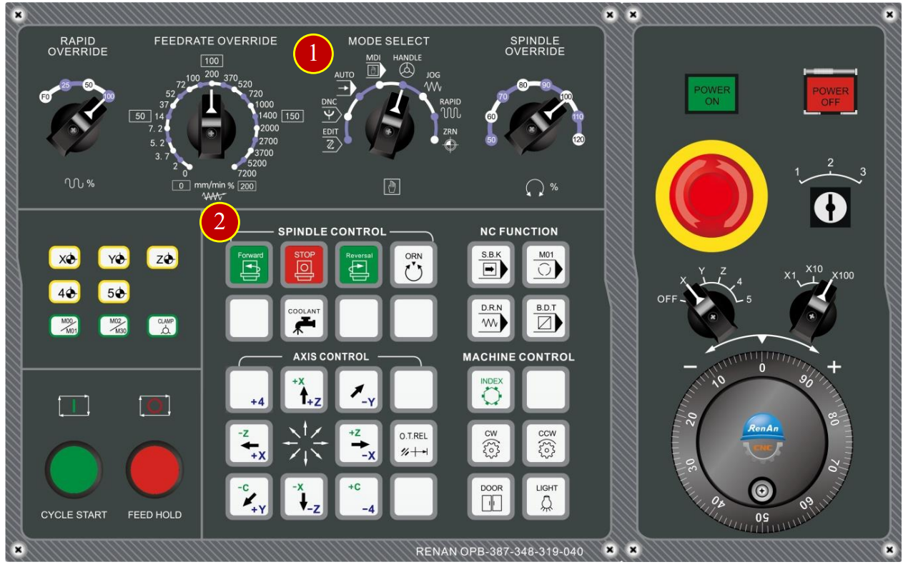
(4) Move tool upward to the External diameter of the Workpiece (+X direction)
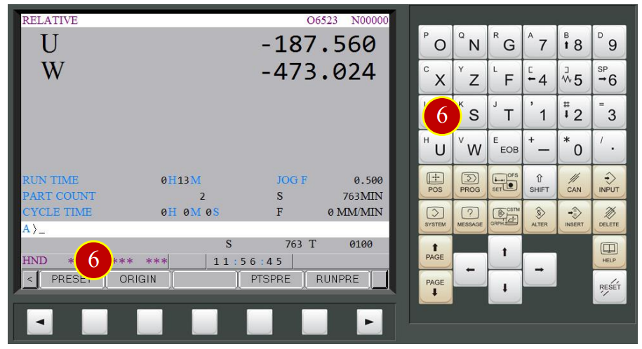
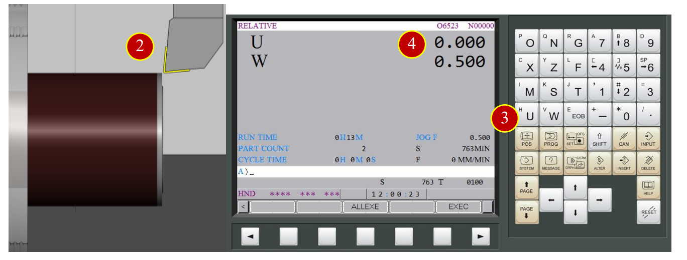
(5) Press【POS】to display the coordinate position,
press【REL】to open the relative coordinate page, then press【(OPRT)】
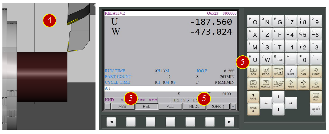
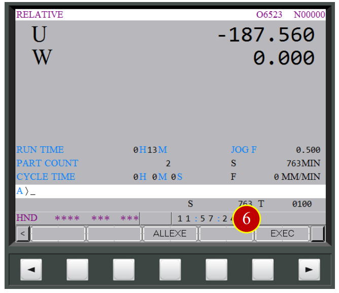
(6) Set W coordinate as 0, press【W】> 【ORIGIN】>【EXEC】,
W coordinate will be set by 0
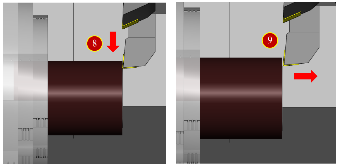
(7) Move tool leftward W-0.5( Cut End Face 0.5mm deeper)
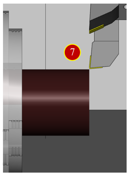
(8) Cut downward (in the –X direction) for about 15mm
(9) Move right (in the +Z direction) to leave the workpiece
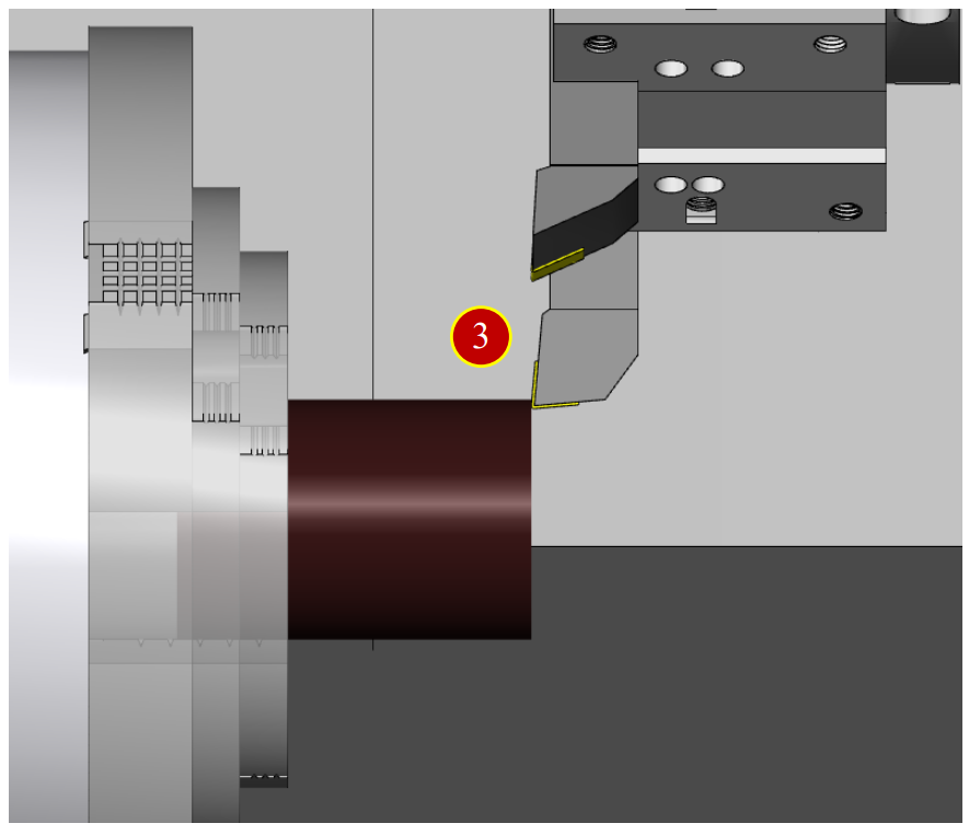
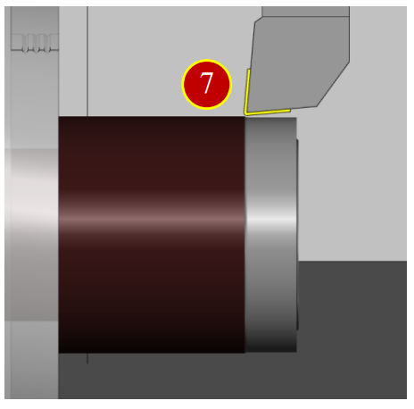
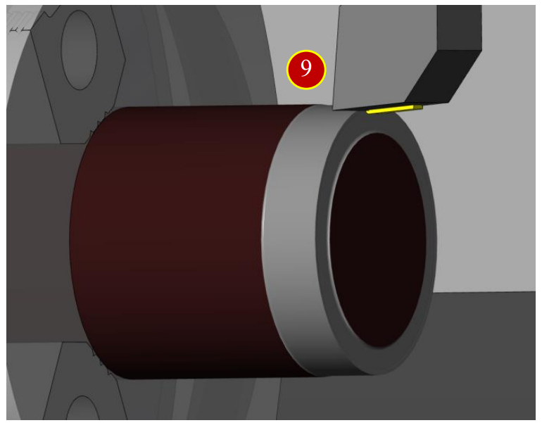
7.2.5 Cut the reference external diameter
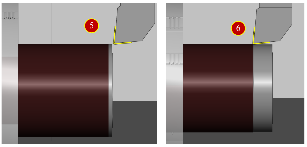
(1) Move the tool to top of the Workpiece, where about 3mm left to the end face.
Slightly attached to the external diameter (till chips and cuts appear)
(2) Move the tool rightward (in the +Z direction) to the Workpiece end face.
(3) Press【POS】to display the coordinate position,
press【REL】to open the relative coordinate page.
(4) Set the U coordinate value 0, press【(OPRT)】>【ORIGIN】<【EXEC】,
the U coordinate will be set by 0
(5) Move tool downward to the X axis U-0.5 (Cut external diameter 0.5mm deeper)
(6) Move leftward in (-Z) direction, cutting for about 15mm
(7) Retract the tool in (+X) direction for about 1 mm
(8) Move the tool leftward in (+Z) direction away from the Workpiece for about 100mm,
press【Spindle Stop】
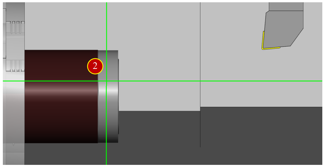
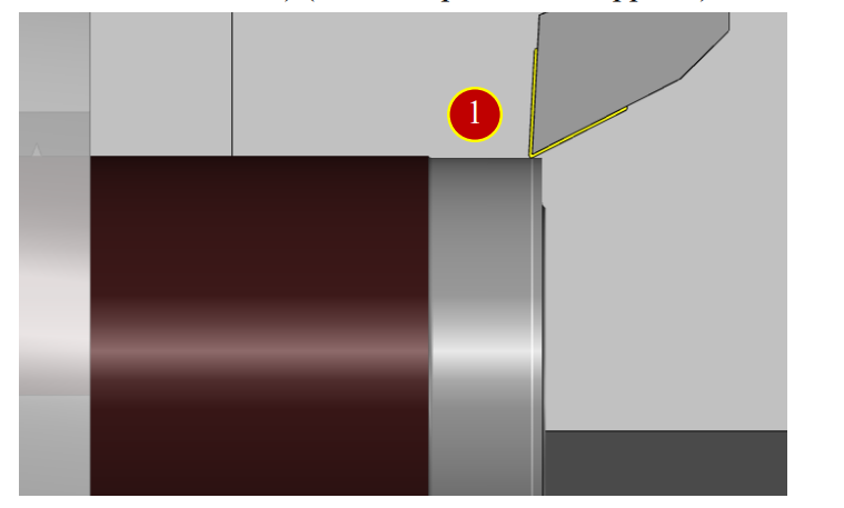
7.2.6 External Diameter Measurement
(1) Press【Meas. Tool】to open the dimension measurement auxiliary function
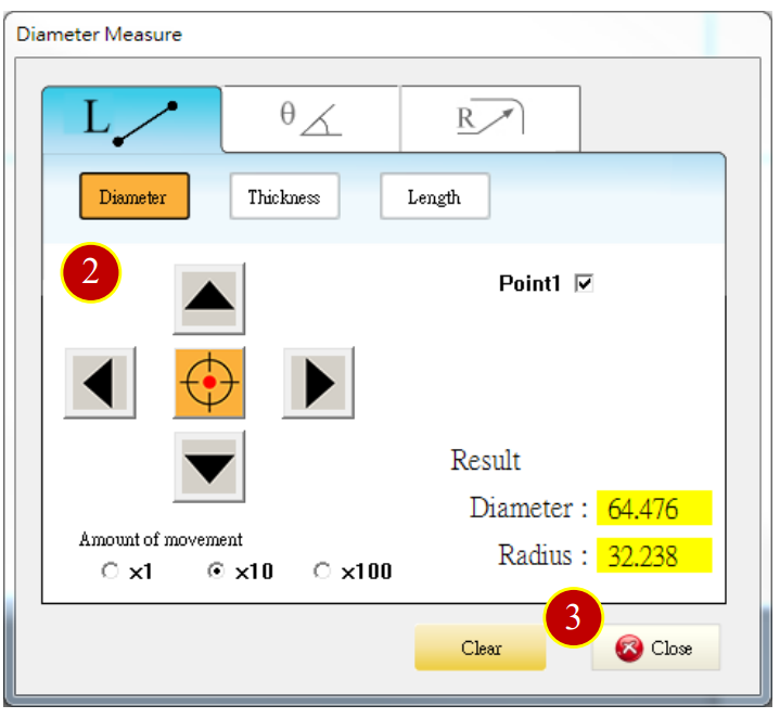
(2) Use Arrow keys and Select button of measurement panel to press the cut outside diameter, the result diameter is 64.476
(3) Press【Close】to close the window
7.2.7 Work Shift Coordinate Setting (Master Tool)- Z axis operation
Select External Rough Tool
Take No.1 tool (default) as example to introduce the offset method
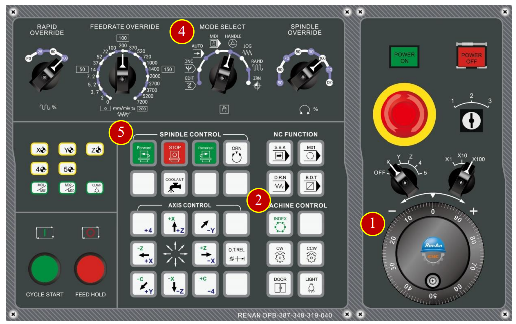
(1) Switch to【RAPID】mode and move the turret to Safe Tool Change position
(2) Press【INDEX】to rotate to tool No.1
(3) Before manual operation, switch【RAPID OVERRIDE】to 50% (or 25%)
(4) Use Axis keys to move the tool to the position
about 50mm left to the workpiece

(5) Switch to【HANDLE】mode
(6) Press【Forward】to rotate the spindle forward
(7) When the tool is about 15mm above from the workpiece,
set the handwheel feed rate to x100
When the tool is about 15mm below from the workpiece,
set the handwheel feed rate to x10
Select X axis or Z axis and rotate the handwheel toward negative direction (-)
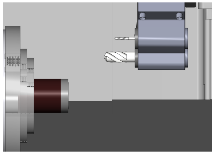
(8) Rotate【Handwheel】to move the tool to workpiece end face,
about 5mm below the max external diameter
(9) Move the tool toward –Z direction and stop when it cut the workpiece end face lightly.
Retract two scales (0.02mm)
Note: When chips and cuts appear, it means the workpiece is cut)
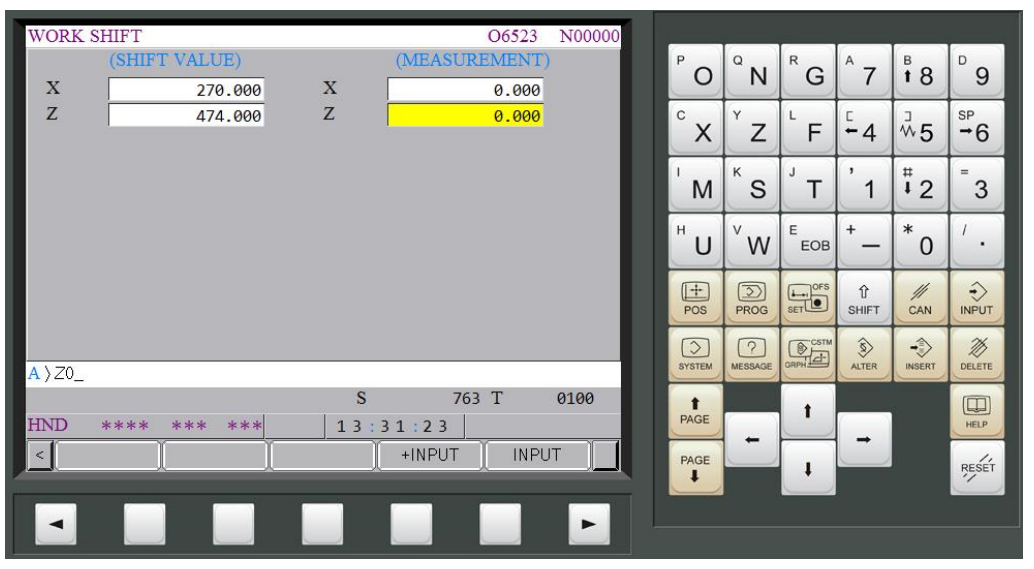
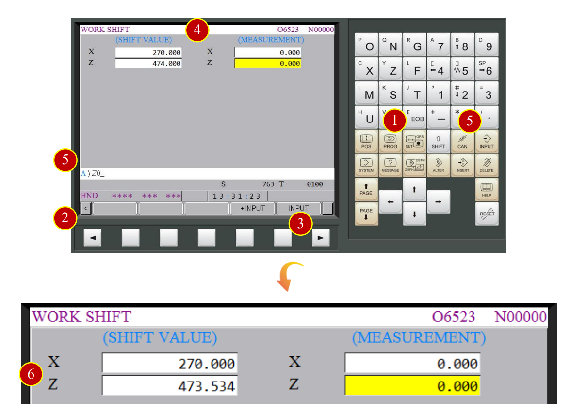
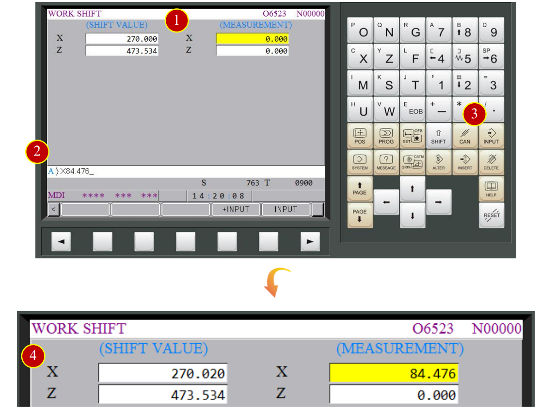
7.2.8 Work Shift Coordinate Setting (Master Tool)- Z Axis Operation
(1) Press【OFS/SET】offset button
(2) Press【 】of left corner to return to the first page of function options window
(3) Press【 】to flip two pages and enter【WORK SHIFT】setting window
(4) Move the cursor to the measurement Z column
(5) Key in “Z0” and press【INPUT】
(6) When the shift value shows up Z= 473.534, Z axis work shift setting is done
7.2.9 Work Shift Coordinate Setting- X Axis Operation
Take Drill No.9 as the example (Drill default size=20mm) to describe the offset method
(1) Switch to【RAPID】mode and adjust Rapid override to 50%
(2) Move the tool carriage to the Safe Tool Change position
(about 150mm left to the workpiece)
(3) Press【INDEX】to rotate to tool No.9
(4) Use the Axis keys to move the tool
to the position about 50 mm left to the workpiece Endface
(5) Switch to【HANDLE】mode
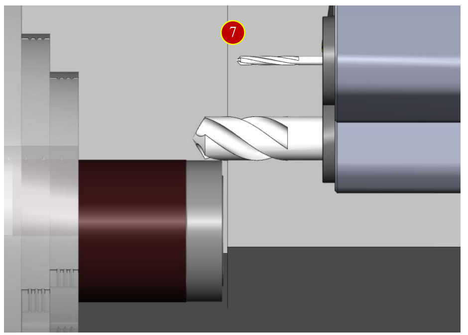
(6) Rotate handwheel to move Tool Setter above the external diameter,
about 10mm left to the end face
(7) Move the tool toward the –X direction and slightly attach the external diameter
(till chips and cuts appear), and retract two Scale (0.02mm)
7.2.10 Work Shift Coordinate Setting (Master Tool)-X Axis Setting
(1) Move cursor to the measurement X column
(2) Key in X 84.476
(a) (64.476+20=84.476)
(The measured material diameter= 64.476mm, Drill diameter= 20mm)
(3) Press【INPUT】
(4) When work shift value shows up X=270.006, it means the work shift setting of X axis is done
*Note: The distance between the carriage center to spindle center line is provided,
it is necessary to key in the value in the X axis work shift column without offsetting
7.3 Z Axis Tool Offset (Offset)
7.3.1 Tool Geometry Offsetting (Each Tool-Turning Tool)-Z Axis Offset Operation
Set the geometry offset of each tool.
Take tool No.2 as the example, introduce the offset method.
(1) Move tool carriage to Safe Tool Change position (about 150mm left to the workpiece)
(2) Press【INDEX】to switch to tool No.2
(3) Use Axis keys to rapid traverse the tool to the position about 50mm left to the workpiece
(4) Switch to【HANDLE】mode
(5) Press【Forward】
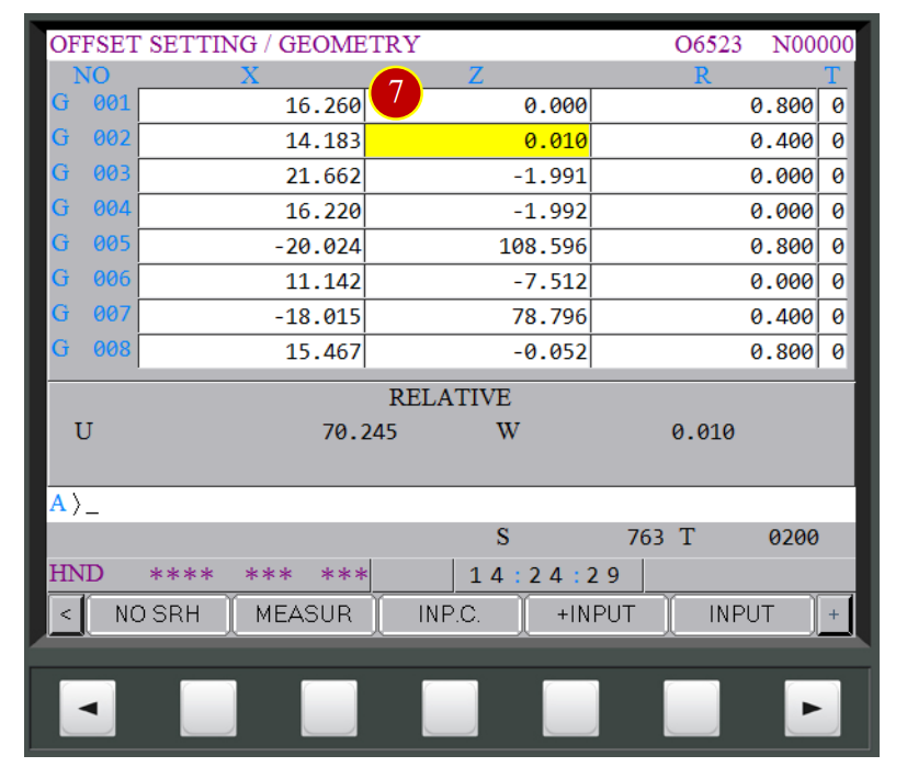
7.3.2 Tool Geometry Offset Setting (Each Tool-Turning Tool)-Z Axis Offset Setting
(1) Press【OFS/SET】via controller panel to display Offset setting window
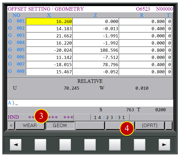
(2) Press【OFFSET】to open the offset window
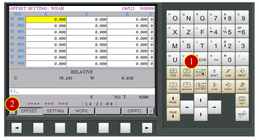
(3) Press【GEOM】to display the geometry offset of each tool
(4) Press【(OPRT)】to display auxiliary function
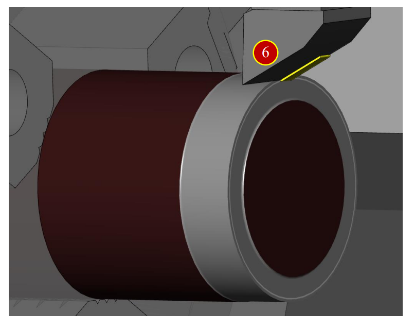
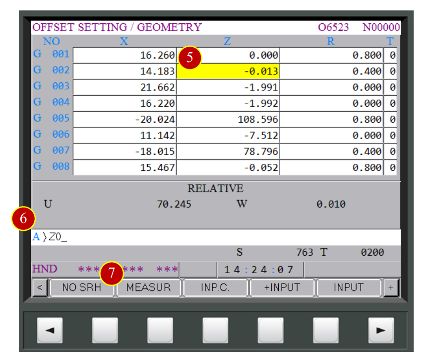
(5) Move the cursor to the position of current offset tool G002
(6) Key in “Z0”
(7) Press【MEASUR】. When the column displays 0.010,
it means Z axis offset has completed
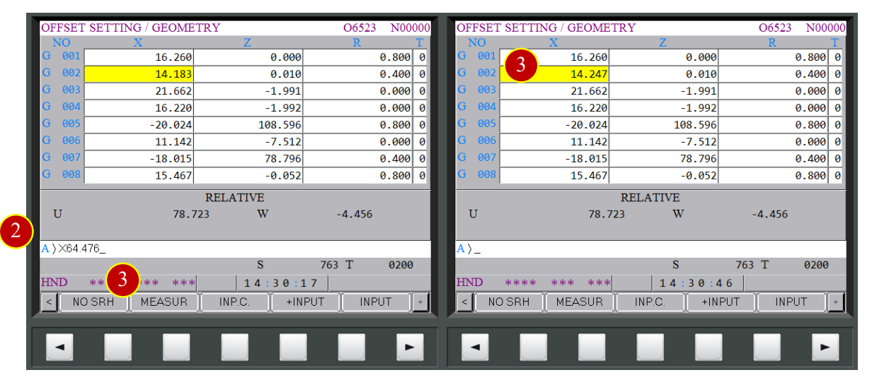
7.3.3 Tool Geometry Offset (Each Tool-Turning Tool) - X Axis Offset
(1) Rotate handwheel to slightly attach the tool to the external diameter
(About 5mm left to the Endface) (Untill chips and cuts appears)
(2) Key in the measured external diameter value “X64.476”
(3) Press【MEASUR】and when it displays X=14.247, it means X axis offset has completed
(4) Offset the Geometry Offset of all the desired tool with the method mentioned above
(Note: Compare the elongation to other external tool as dimension reference)
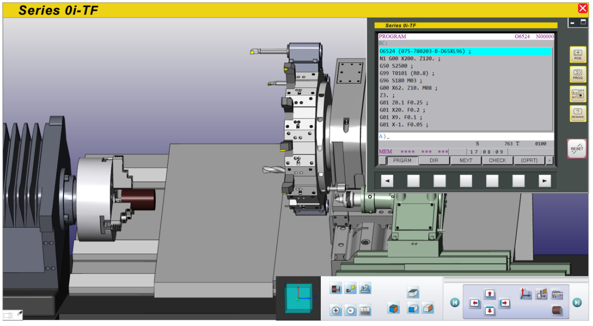
7.4 Auto-Run
7.4.1 Start the Program
Use Auto-Run to execute program
(1) Switch the mode to【AUTO】
(2) Press【PROG】
(3) Key in the NC code that is desired to simulate
e.g. O6524
(4) Press【 】search button to open and display the program
(5) Press【 】to return to preivious menu
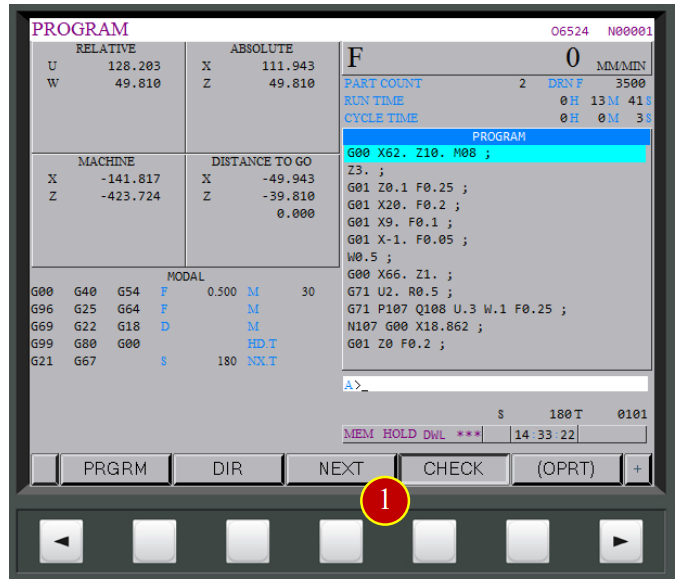
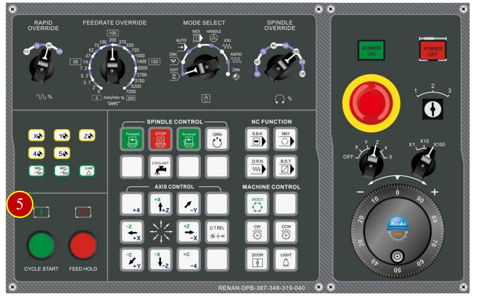
7.4.2 Program AUTO Run
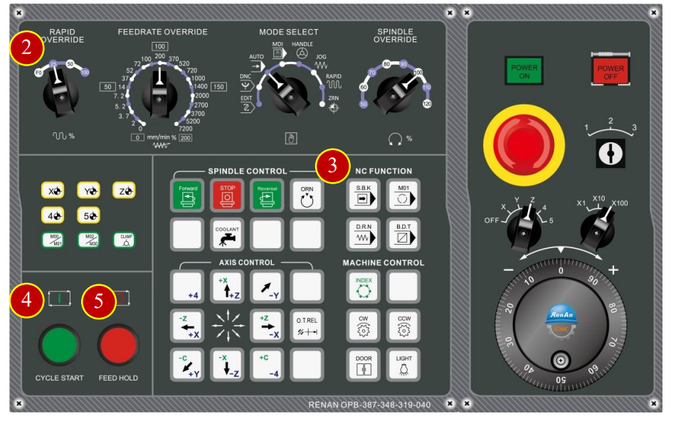
(1) Press【CHECK】to display coordinates and program
(2) Switch【RAPID OVERRIDE】override knob to 25%
(3) Press【S.B.K】(Light up means it is functional)
(4) Press【CYCLE START】to run the program
(5) Watch the tool moving and when the tool is approach the workpiece (about 50mm)
press【FEED HOLD】immediately to stop the tool
(6) Check if the position of the tool and workpiece matches the size of program coordinates
e.g. Program Absolute Coordinates Z= 39.810 ,
about 40mm left to the workpiece by vision
(7) Press【CYCLE START】to continue the process
(8) When the tool gets closer to the workpiece (about 20mm ),
press【FEED HOLD】to pause the feed
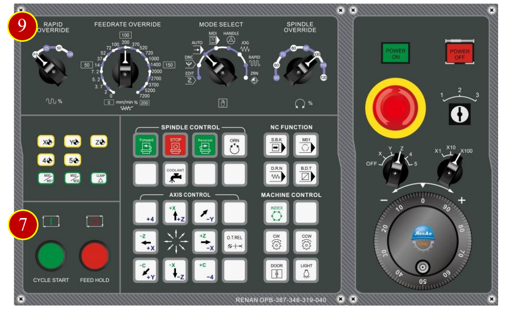
(9) Switch【RAPID OVERRIDE】override knob to 0F position
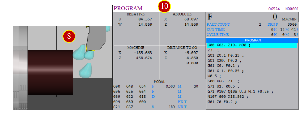
(10) Check if the position of the tool and workpiece matches the size of program coordinates
e.g.
Program Absolute Position Distance to go
X= 62.000 X= - 0.000
Z= 14.860 Z= - 4.860
(11) Press【CYCLE START】to continue programing till the cutting process is done.
*Caution:
(a) During the process of trial cutting,
as long as the process is within the approaching range of the tool and workpiece,
keep Rapid Traverse at F0 position for the sake of safety
(b) Press【FEED HOLD】first whenever feel something goes wrong, examine later
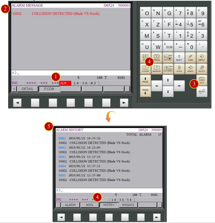
7.5 Machine Alarm
When the error occurs, alarm will display on the controller panel
7.5.1 ALARM Clear
(1) When the controller panel displays “ALM”
(2) Check the alarming code and messagest, then clear the errors according to its messages
(3) Press【RESET】to clear the alarm after getting the errors messages
(4) Press【HISTORY】in【MESSAGE】to check history record
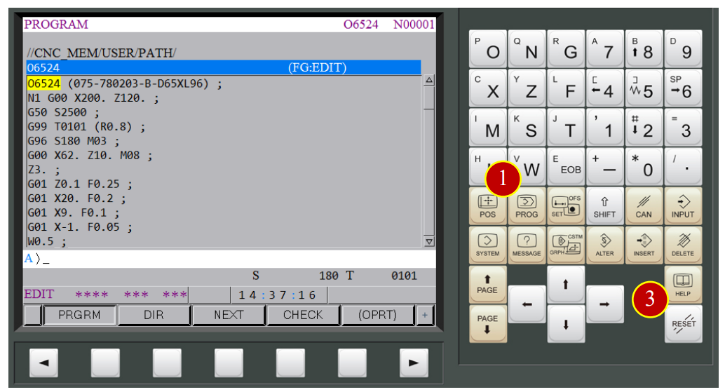
7.5.2 Return to AUTO Run
When the program is interrupted, or trying to return to AUTO Run window
from the alarm notification window
(1) Press【PROG】to return to the program display window
(2) Switch to【EDIT】mode via Modal Select
(3) Press【RESET】and position the cursor back to the begin of the program
(4) Reselect the needed operation mode
e.g.【AUTO】mode
(5) Make sure the cursor is at the begin of NC code
and press【CYCLE START】to AutoRun
Get free trial now!
1.Register as RenAn member
2.Get free trial_VM Fanuc 0i-TF
3.Contact RenAn for more information: service@renan.com.tw
文章區塊