
CH7_Machine Basic Operation_Fanuc Milling
today
2024-11-04
local_offer
Fanuc Milling
visibility
3234
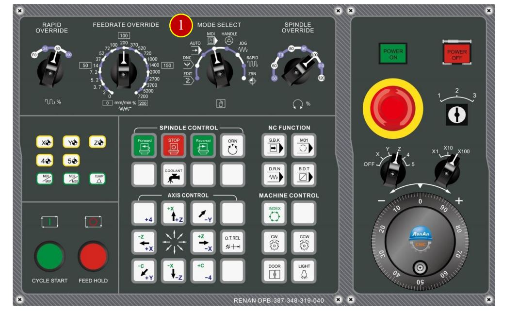
7. Machine Basic Operation
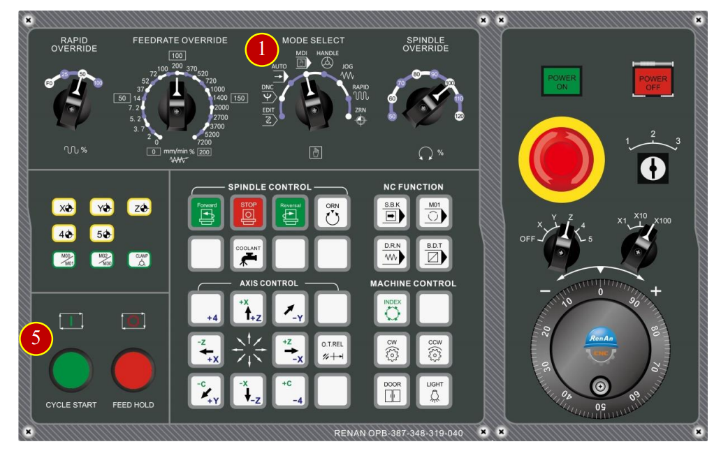
7.1 ZRN Operation
Please do return each axis to the home position in order to establish a reference position
For the coordinate auto-run movement.
7.1.1 Operation Steps
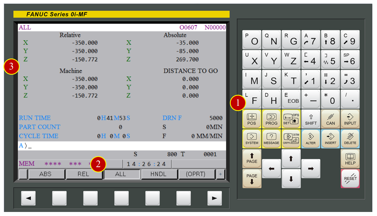
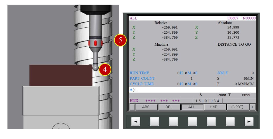
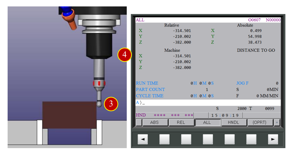
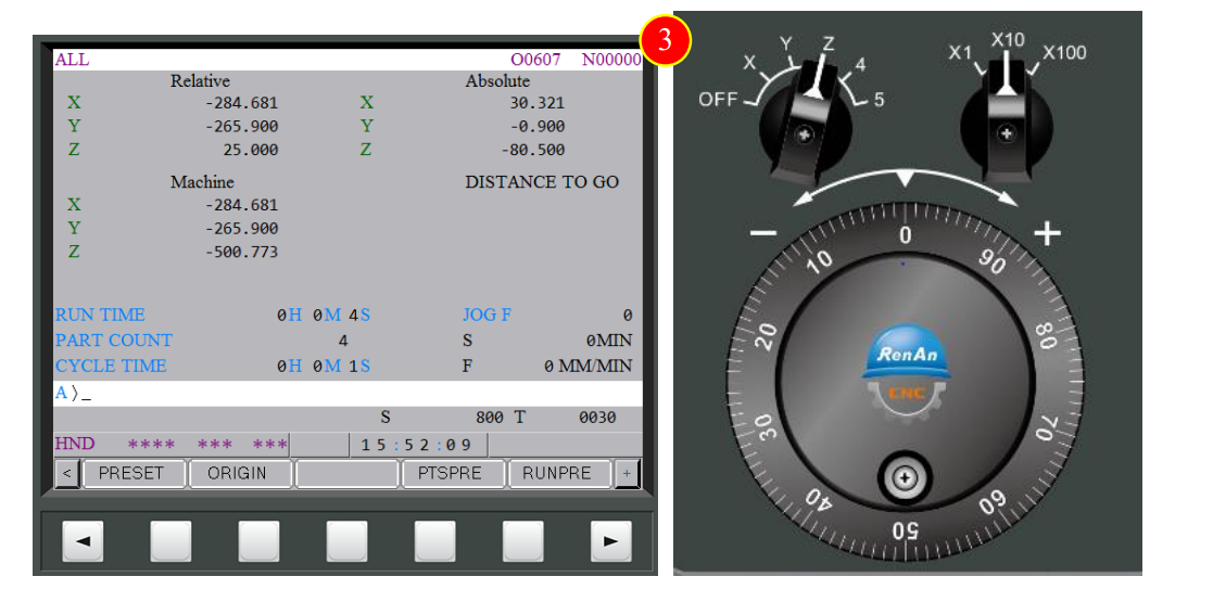
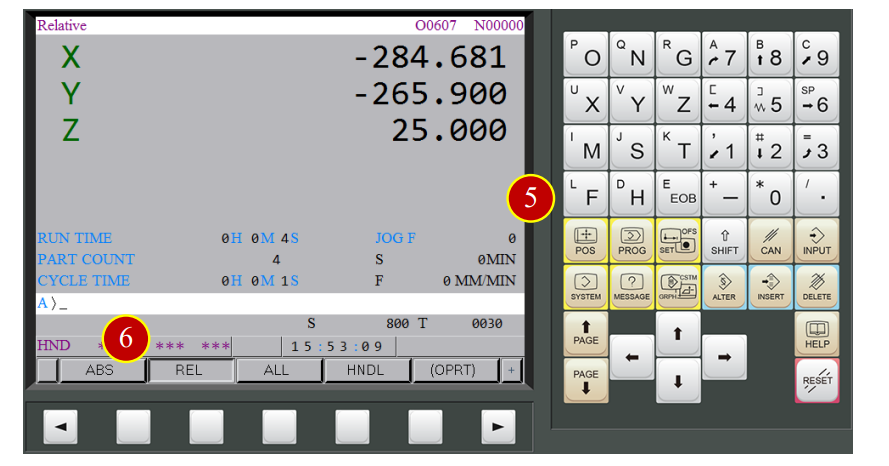
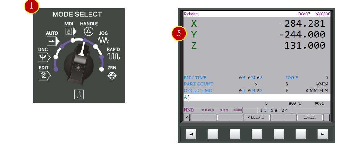
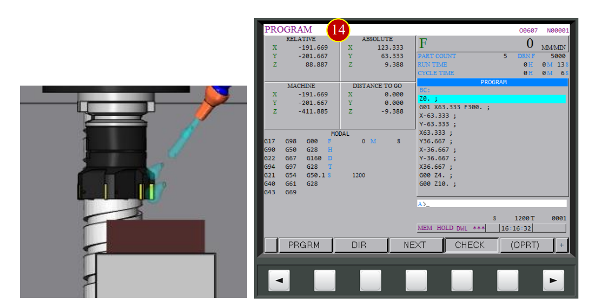
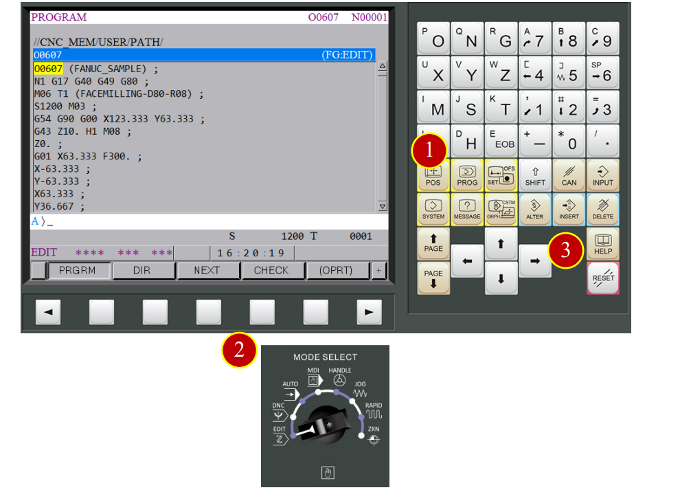
(1) Press【POS】to display the coordinate function button.
(2) Press【ALL】to display all of the coordinate value.
(3) Check Machine Coordinates Value:
RELATIVE : The coordinate value based on the assigned position
ABSOLUTE : The coordinate value based on Cartesian coordinate zero point
MACHINE : The point that is specific to a machine and serves
as the reference of the machine is referred to as the machine zero point
DISTANCE TO GO: Shows the distance from the current tool position.

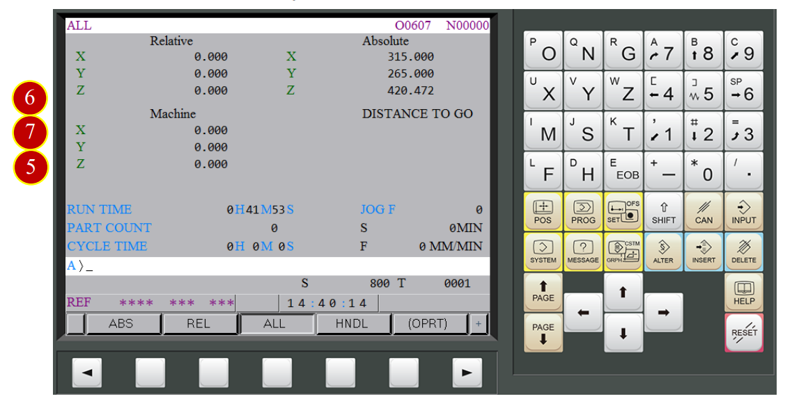
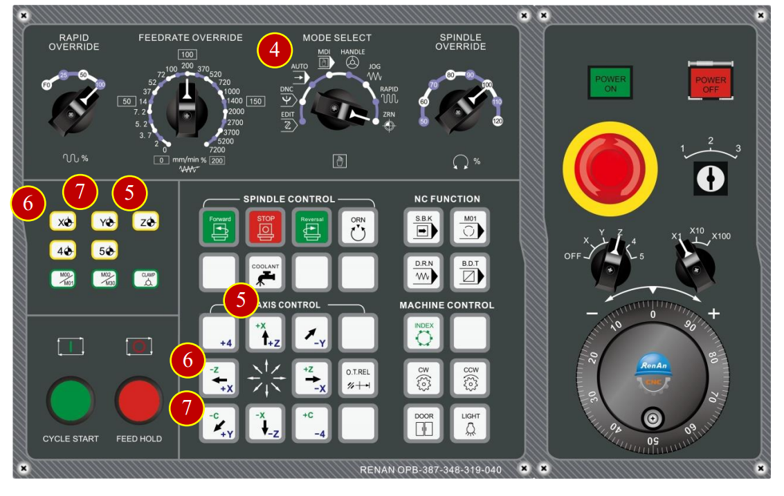
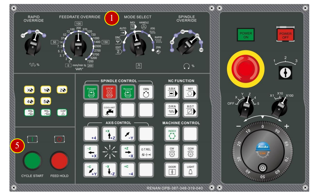
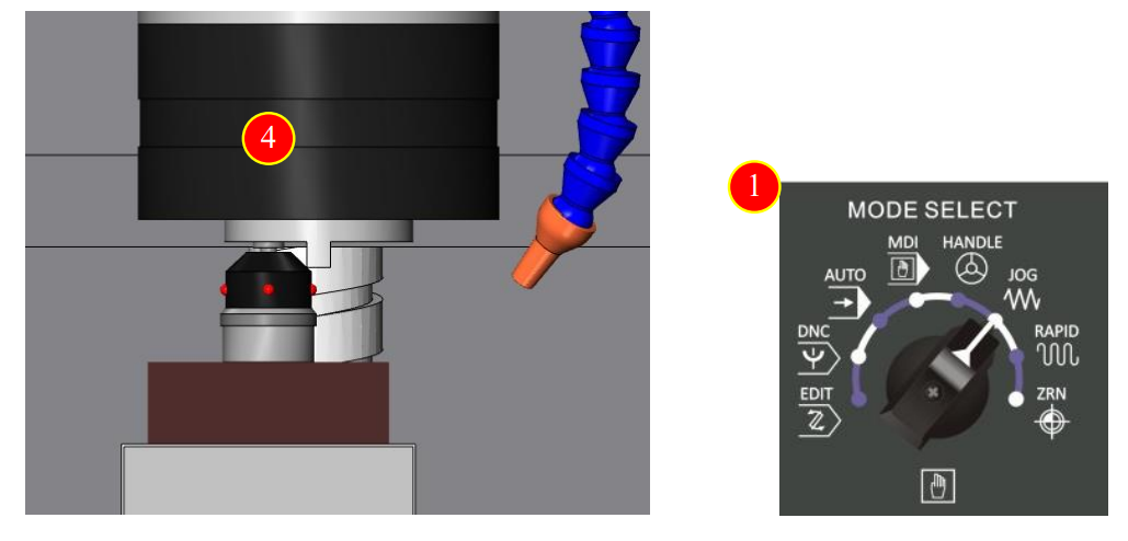
(4) Change to【ZRN】mode (Zero Return).
(5) Press [+Z] of the Axial Movement Panel, Z axis starts to move toward reference point,
When ZRN light up means the Z axis has return to reference point,
and machine coordinate is 0
(6) Press [+X], X axis starts to move toward reference point rapidly
When ZRN light up means X axis has return to reference point,
and machine coordinate is 0.
(7) Press [+Y], Y axis starts to move toward reference point rapidly
When ZRN light up means the Y axis has return to reference point,
and machine coordinate is 0
7.2 Work Coordinate Setting (Offset)
7.2.1 Definition of Work Coordinate
Controller needs to set accurate zero point in order to cut correctly.
In general, the zero point of work coordinate is built at the center position
on the top of the workpiece in milling
(1) Need to reset the correct work coordinates after changing workpiece
(2) Need to reset the tool geometry (length) offset value after changing tool
(The figure which takes the spindle conical degrees major diameter as the reference tool length)
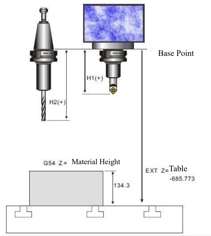
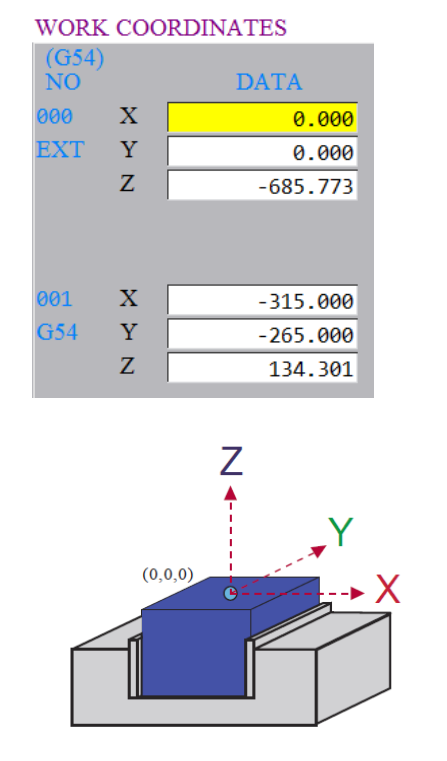
EXT X = Not used. (Generally set as zero)
EXT Y = Not used. (Generally set as zero)
EXT Z = The machine coordinate between bottom of spindle head to the bed
Zero point of work coordinate:
G54 X =The value of axis X machine coordinate (generally in negative number)
G54 Y= The value of axis Y machine coordinate (generally in negative number)
G54 Z= Machine coordinates is based on the point from the bottom of the spindle
to the top of the workpiece
(H) = Length of each tool
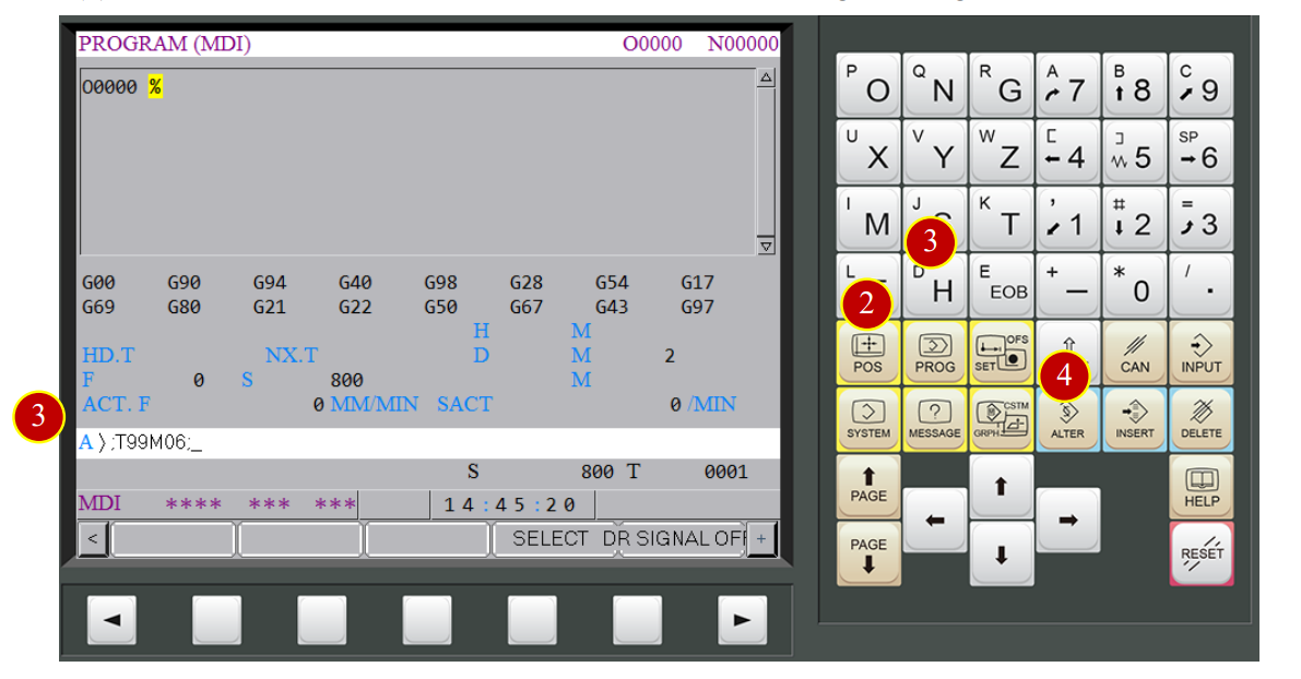
7.2.2 Work Coordinate Setting –Use Edge Finder
Change tool to edge finder, NO.99 is the default tool
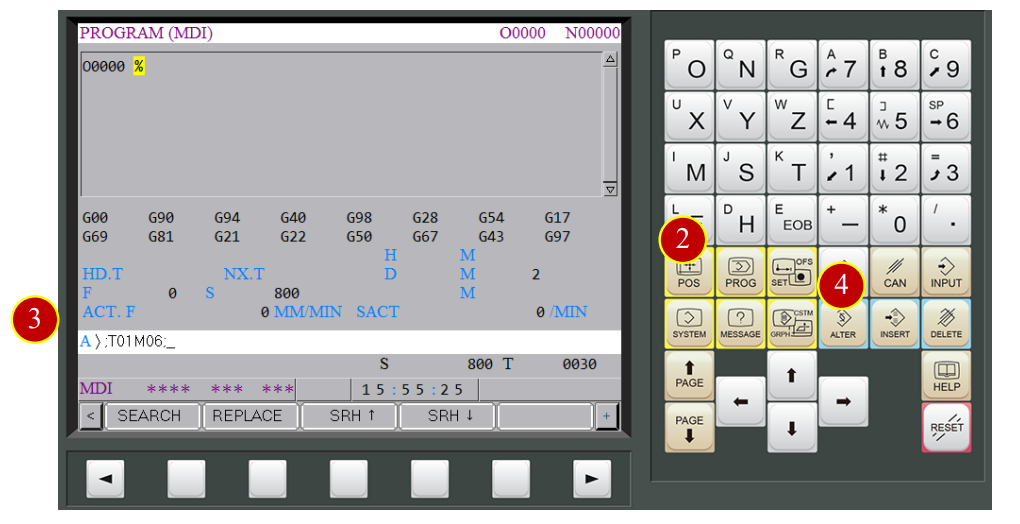
(1) Change mode to【MDI】
(2) Press【PROG】
(3) Key in “ ;T99M06; ” [EOB] Code= (;)
(4) Press【INSERT】
(5) Press【CYCLE START】, the current tool will be changed to edge finder.
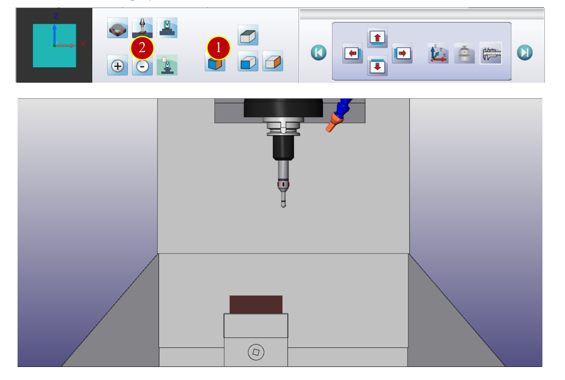
7.2.3 Adjust View
Adjust the view to the proper angle and size for offsetting
(1) Press【Front View】button
(2) Press【Hide/Display Machine Shell】button to hide the machine shell
7.2.4 Work Coordinate Setting- X axis
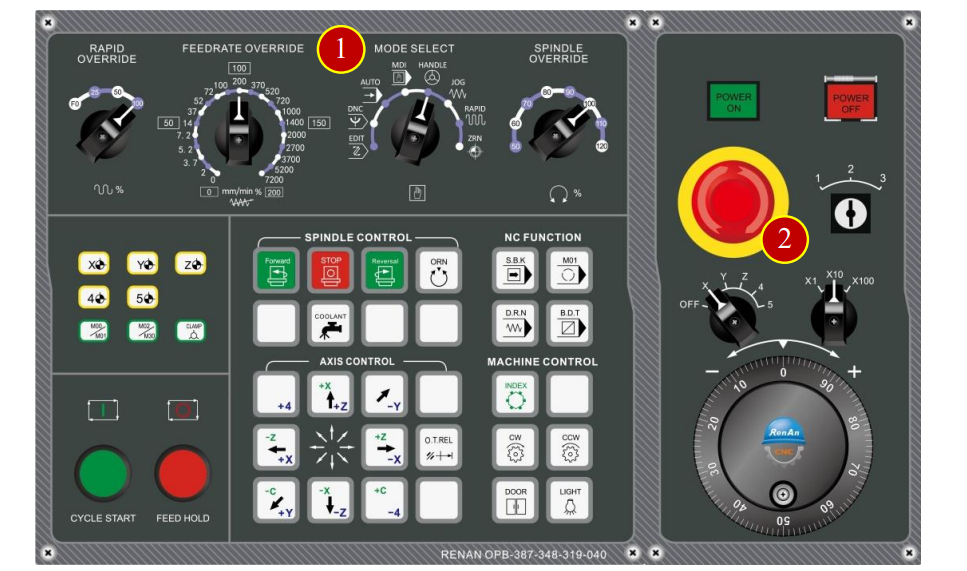
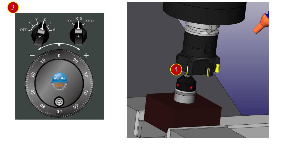
(1) Change to【HANDLE】mode
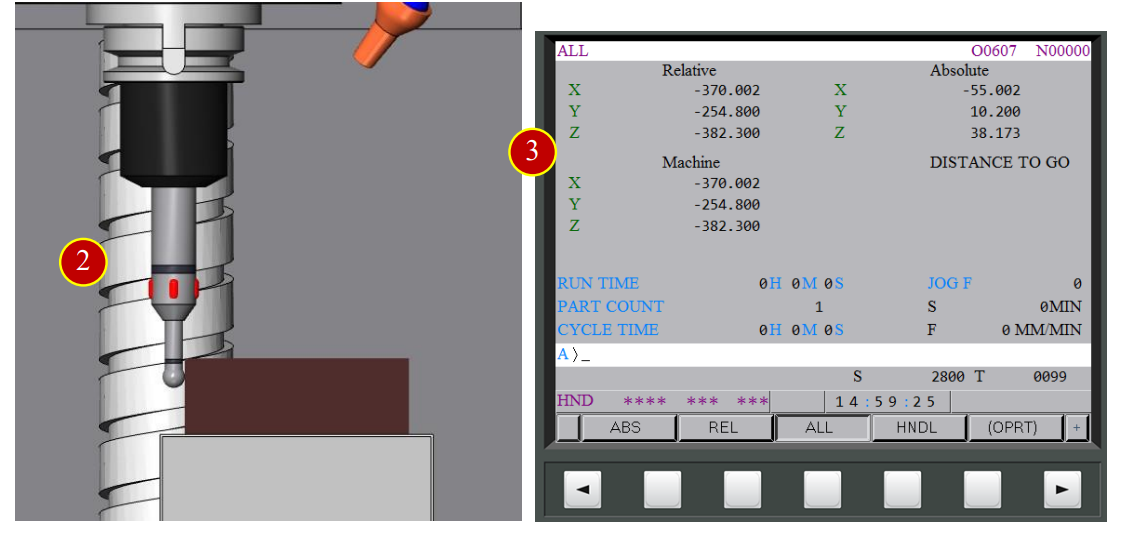
(2) Use edge finder to touch the workpiece from left side and measure the needed position
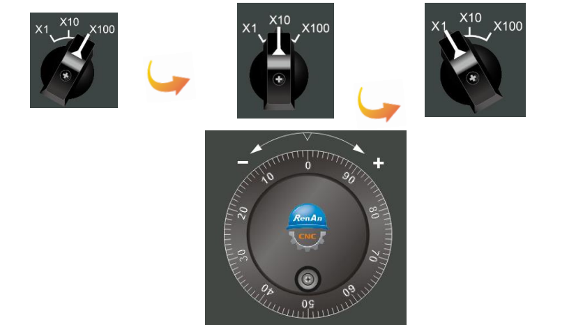
(a) Use Handwheel and switch Handwheel feedrate to x100
(b) Touch the workpiece with edge finder, stop when light up
(c) When rotating the Handwheel one scale back and the light is off,
switch Handwheel feedrate to x10.
(d) Touch the workpiece with edge finder, stop when light up
(e) When rotating the Handwheel one scale back and the light is off,
switch Handwheel feedrate to x1
(f) Touch the workpiece with edge finder again, stop when light up
(g) Move the tool by rotating the Handwheel accurately to the position where the setter’s signal light presents on and off in one scale rotation
(3) Check and record current machine coordinate X e.g. -370.002
(4) Use edge finder to touch the workpiece from right side, and measure the needed position
(5) Check and record current machine coordinate X e.g. -260.001
(6) The average of the two coordinates will be the center of X axis
e.g. X Axis work coordinate offset value (-370.002-260.001)/2=-315.002
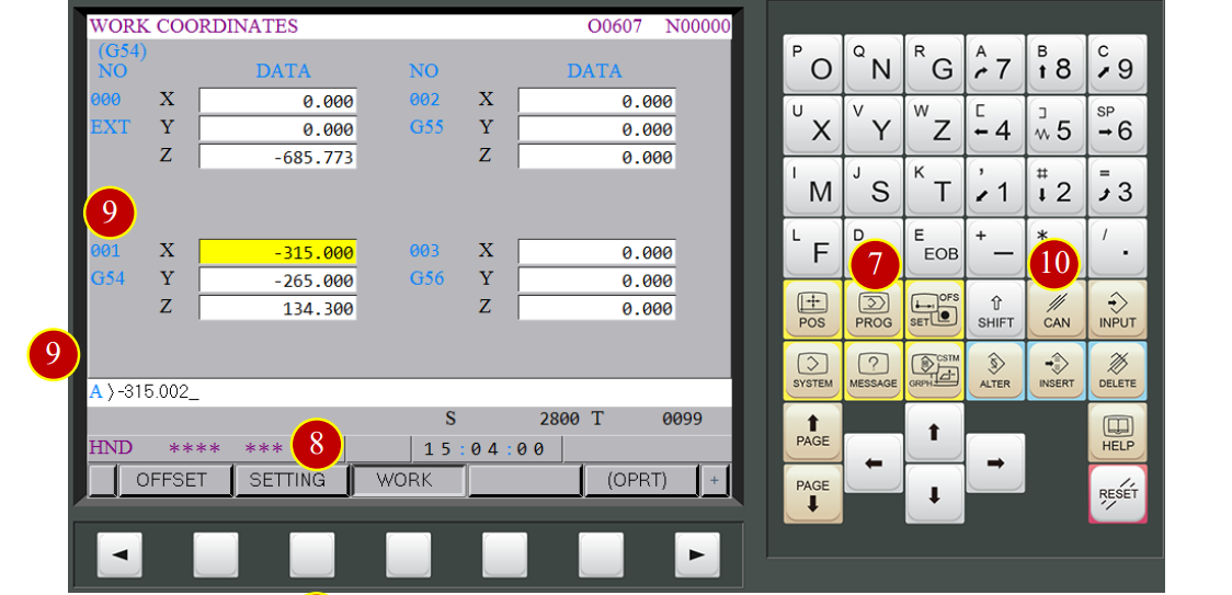
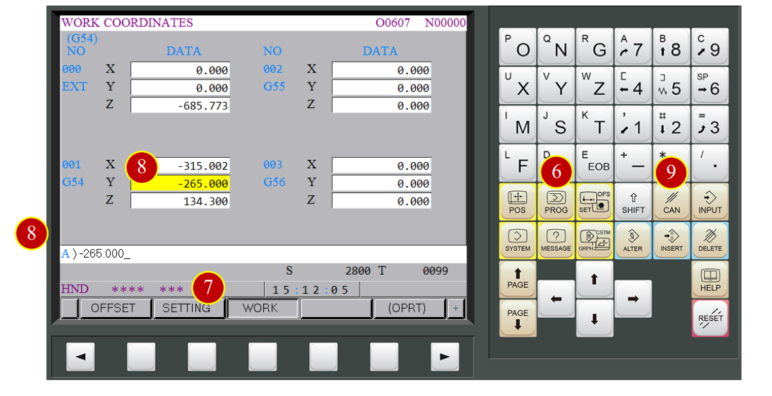
(7) Press【OFS/SET】
(8) Select【WORK】
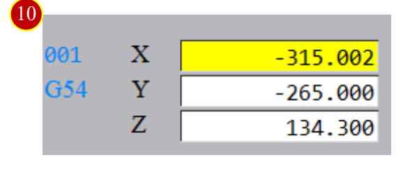
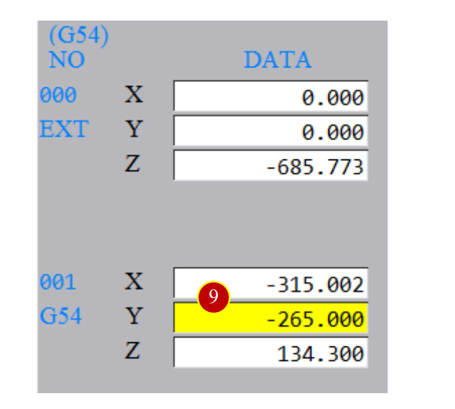
(9) Move cursor to X column of G54 , key in -315.002
(10) Press【INPUT】to finish X axis work coordinate offset value calculation
7.2.5 Work Coordinate Setting- Y axis
(1) Use Handwheel to move edge finder to touch the workpiece from the front and measure the needed position
(2) Check and record current machine coordinate Y e.g.-319.998
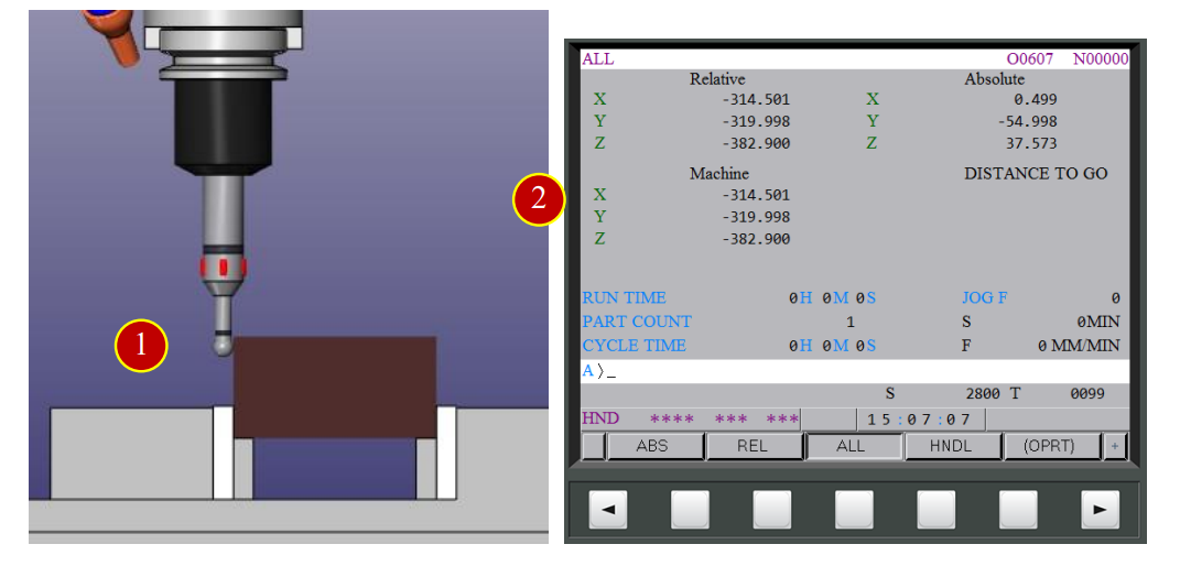
(3) Use edge finder to touch the workpiece from the back and measure the needed position
(4) Check and record current Y machine coordinate e.g.-210.002
(5) The average of two coordinates value will be the center of Y axis
e.g. Y axis work coordinates offset value, (-319.998-210.002)/2=-265.000
(6) Press【OFS/SET】
(7) Select【WORK】
(8) Move cursor to Y column of G54, key in -265.000
(9) Press【INPUT】to finish the Y axis work coordinate offset calculation
7.2.6 Work coordinate setting of axis –Relative Zero Point
Use the Tool Setter to measure the distance from button of spindle carriage to the end face of workpiece to calculate the Z axis work coordinate of G54
In order to set up the Tool Setter on the table as the relative zero point, choose the End Mill to do the calculation.
*Take T04 as example:
(1) Change to【MDI】mode
(2) Press【PROG】
(3) Key in “;T04 M06;”
(4) Press【INSERT】
(5) Press【CYCLE START】, the current tool will be changed to T04 End Mill
(6) Change to【Handle】mode
(7) Press【Tool Setter】button and set the Tool Setter above the machine bed
(8) Use Tool Setter to measure the needed position
(a) Use Handwheel and switch Handwheel feedrate to x100
(b) Move tool above the Tool Setter, touch it with tool nose and keep pressing,
stop when the Tool Setter’s signal light is up
(c) When rotating the Handwheel one scale back and the light is off,
switch Handwheel feedrate to x10
(d) Keep rotating Handwheel and pressing down the spindle ,
stop when the Tool Setter’s signal light is up
(e) When rotating the Handwheel one scale back and the light is off,
switch Handwheel feedrate to x1
(f) Keep rotating Handwheel and pressing down the spindle ,
stop when the Tool Setter’s signal light is up
(g) Move the tool by rotating the Handwheel accurately to the position where the setter’s signal light presents on and off in one scale rotation
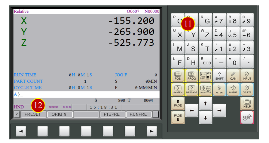
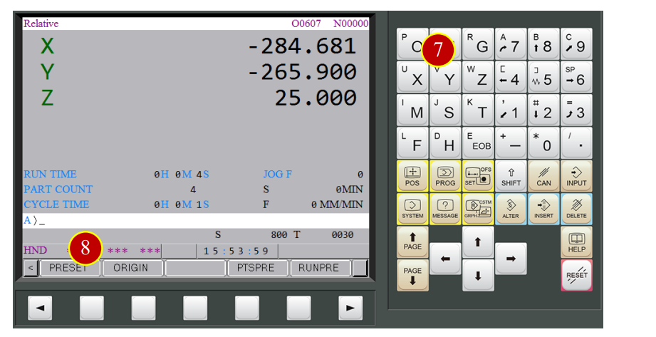
(9) Press【POS】
(10) Press【REL】
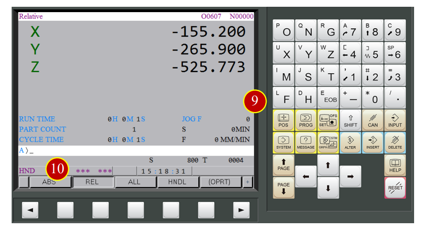
(11) Press【Z】
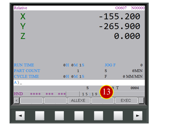
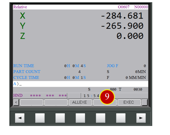
(12) Press【ORIGIN】
(13) Press【EXEC】and the current position is the relative zero point of Z axis
7.2.7 Work Coordinate Setting- Z axis
(1) Press【Tool Setter】button and set the Tool Setter above the workpiece
(2) Rotate Handwheel to move the tool above the Tool Setter
(3) Touch tool with the Tool Setter and keep pressing,
stop immediately when the Tool Setter’s signal light is up
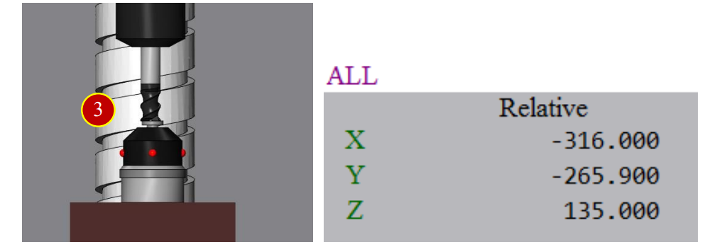
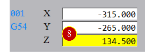
(4) The relative coordinate value Z is the G54 work coordinate value Z
e.g. Relative coordinate Z= 135.000
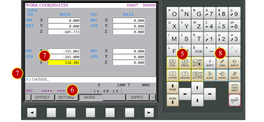
(5) Press【OFFSET】
(6) Press【WORK】
(7) Move the cursor to Z column of G54, key in 134.500
(For Facemilling, save allowance 0.5mm, 135.000-0.5=134.500)
(8) Press【INPUT】and the Z axis work coordinate offset setting is finished
7.3 Tool Offset (OFFSET)
7.3.1 Tool Geometry Offset (Each Tool)
Use Z Tool Setter to measure the length between the spindle carriage and the tool nose,
take No.1 tool as example
When uninstalling the tool, it is necessary to set the spindle carriage to relative zero point, so select the empty tool
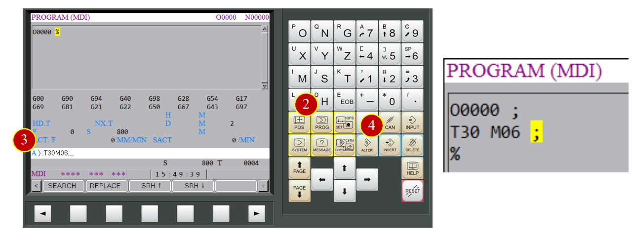
Take T30 as example:
(1) Change to【MDI】mode
(2) Press【PROG】
(3) Key in “;T30 M6;”
(4) Press【INSERT】
(5) Press【CYCLE START】and the tool will be changed to NO. 30 empty tool
7.3.2 Tool Geometry Offset- Relative Zero Point
(1) Change to【HANDLE】mode
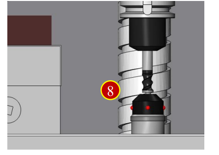
(2) Press【Tool Setter】button and set it above the work
(3) Rotate Handwheel to move the spindle above Tool Setter
Touch the Tool Setter with spindle end face and keep pressing,
stop immediately when the Tool Setter’s signal light is up
(4) Press【POS】
(5) Press【REL】
(6) Press【Z】
(7) Press【ORIGIN】
(8) Press【EXEC】to set the current position as Z relative zero point
7.3.3 Change Tool to be Measured
Use Z Tool Setter to measure the length between the spindle carriage and the tool nose
Take Tool No.1 as the tool geometry offset example
(1) Change to【MDI】mode
(2) Press【PROG】
(3) Key in “;T01 M06;”
(4) Press【INSERT】
(5) Press【CYCLE START】and the current tool will be changed to Tool No.1
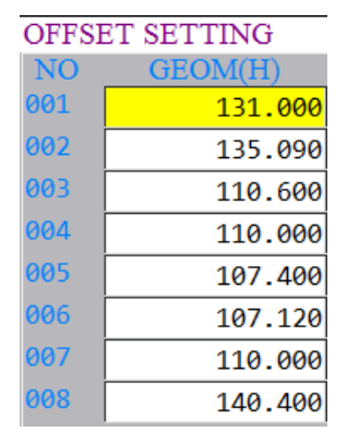
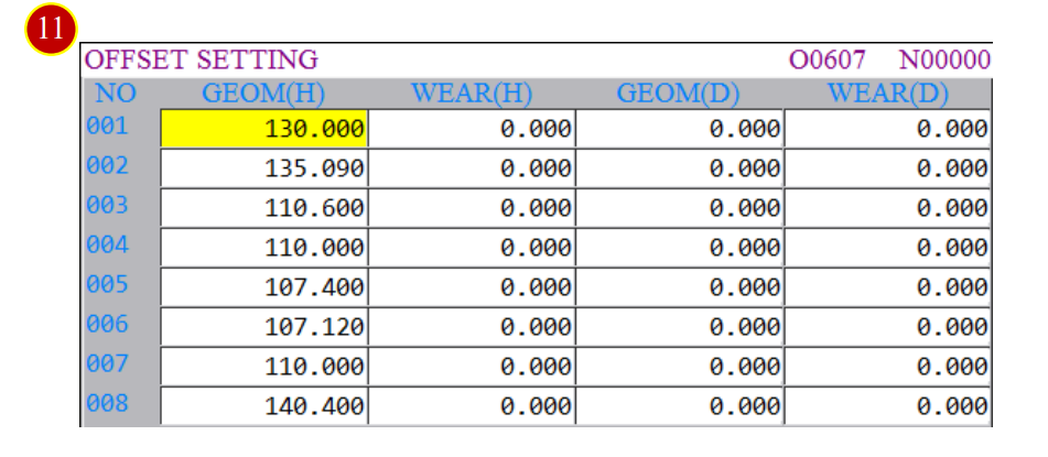
7.3.4 Tool Geometry Offset Setting
(1) Change to【HANDLE】mode
(2) Press【Z Tool Setter】button and set it above the workpiece
(3) Rotate the Handwheel to move spindle above the workpiece
(4) Touch the Tool Setter with tool and keep pressing, stop when the light of Tool Setter is up
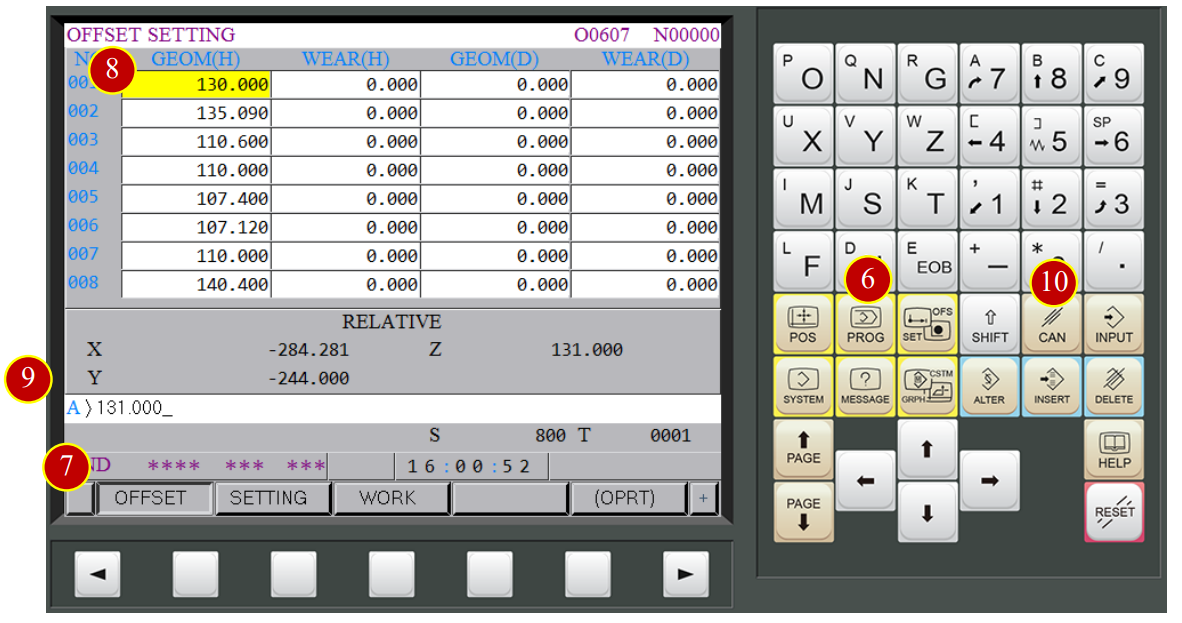
(5) The current Relative Coordinate Z value will be the tool length of tool No.1
e.g.131.000
(6) Press【OFS/SET】button of panel
(7) Press【OFFSET】button
(8) Move cursor to 001 geometry (H) column
(9) Key in 131.000
(10) Press【INPUT】, and the No.1 tool offset is finished
(11) Finish all the geometry offset setting of all the needed tool with the method above
7.4 Auto Run
Auto-RUN the CNC program in the controller
7.4.1 Operation Steps
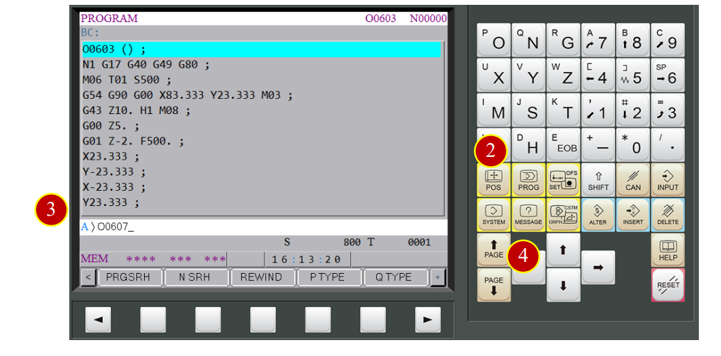
(1) Change to【AUTO】mode
(2) Press【PROG】button
(3) Key in the program number to be simulated
e.g. O0607
(4) Press down arrow button to open the program
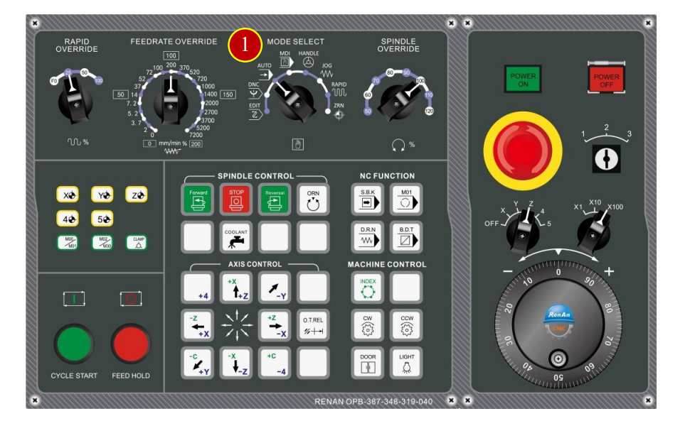
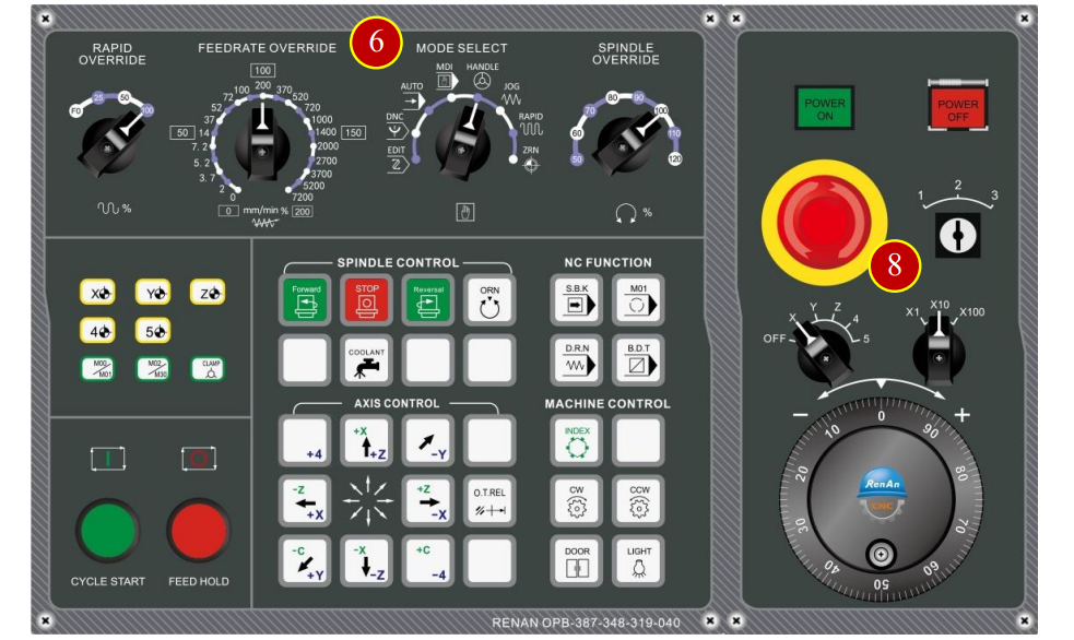
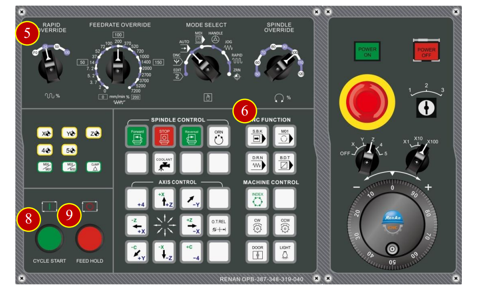
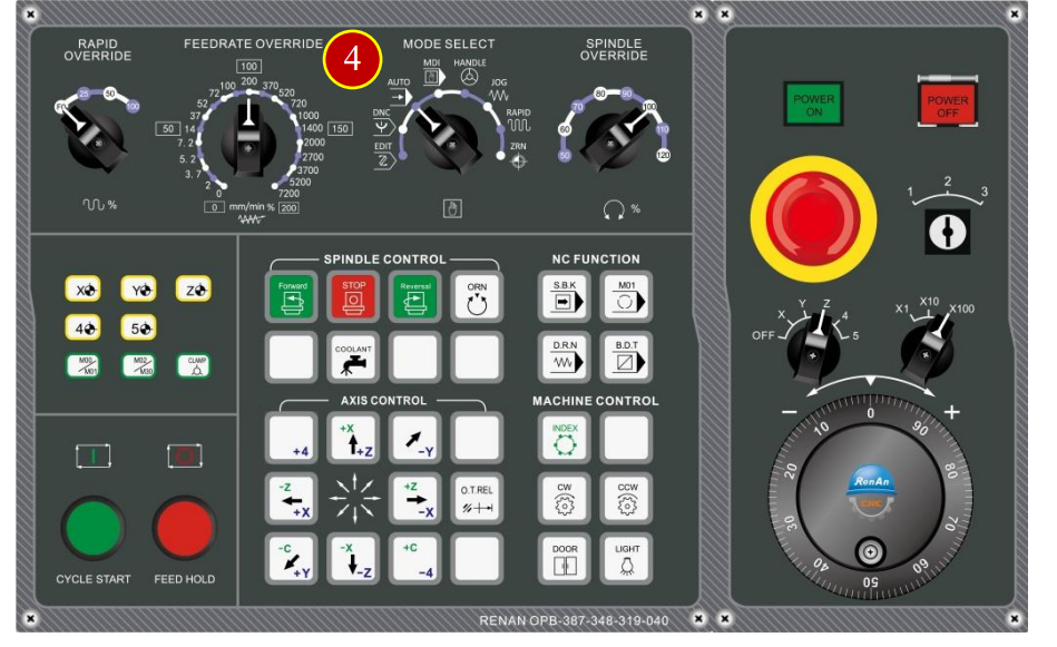
(5) Before auto-run the program, switch【Rapid Override】knob to 25%
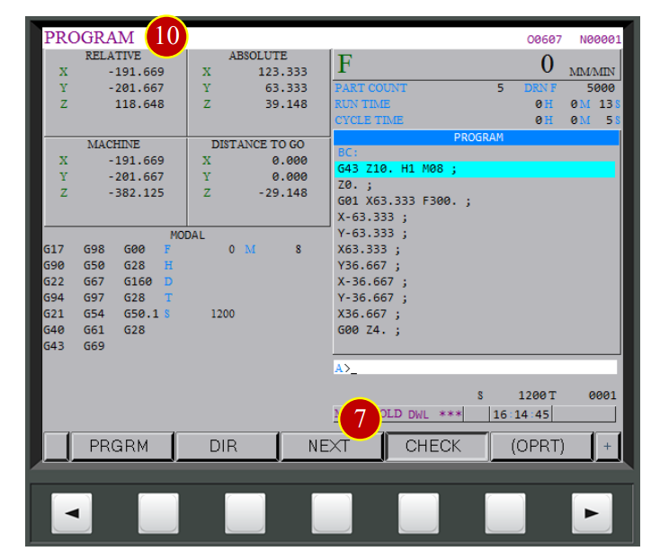
(6) Press【S.B.K】 (Light up means it is enabled)
(7) Press【CHECK】to check the coordinate and CNC code at same time
(8) Press【CYCLE START】to run the program
(9) Watch the tool moving and when the tool is close to the workpiece (about 50mm),
Press【FEED HOLD】immediately to stop the tool cutting movement
(10) Check the position of tool, workpiece and coordinates is identical to the size
e.g. Relative Coordinates Z=39.148,
the tool nose is about 40mm away from workpiece by vision
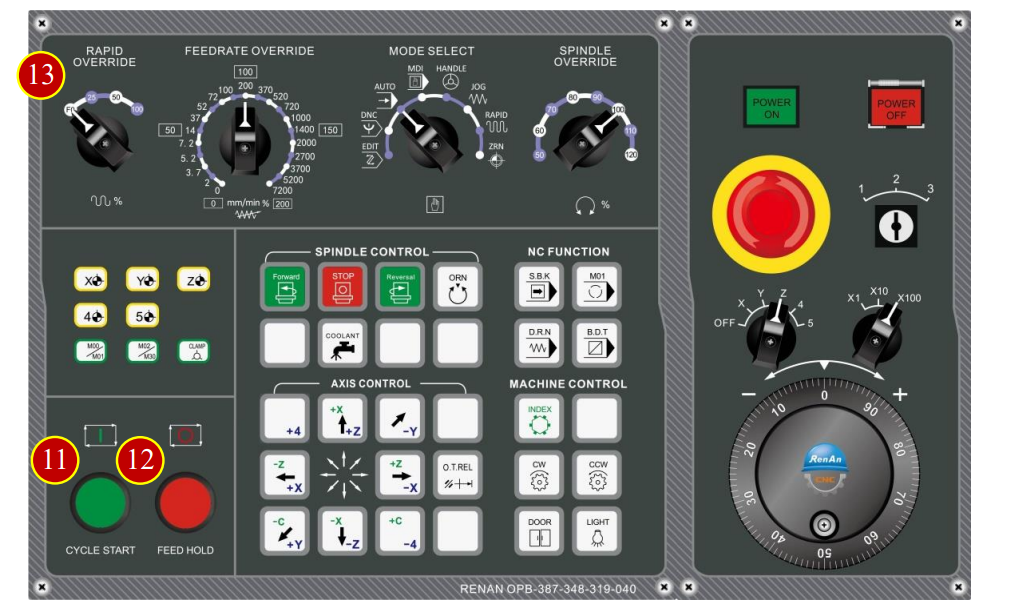
(11) Press【CYCLE START】to continue the program
(12) When the tool is closer to the workpiece (about 10mm), Press【FEED HOLD】
(13) Switch Rapid Override Knob to【F0】
(14) Make sure the position of tool and workpiece is identical to program coordinates
Caution:
(a) When commissioning the machine,
keep the Rapid Feedrate at F0 position as long as the tool is close to the workpiece
(b) Always press【FEED HOLD】button immediately to Pause the machine
whenever feel something wrong, then check the status
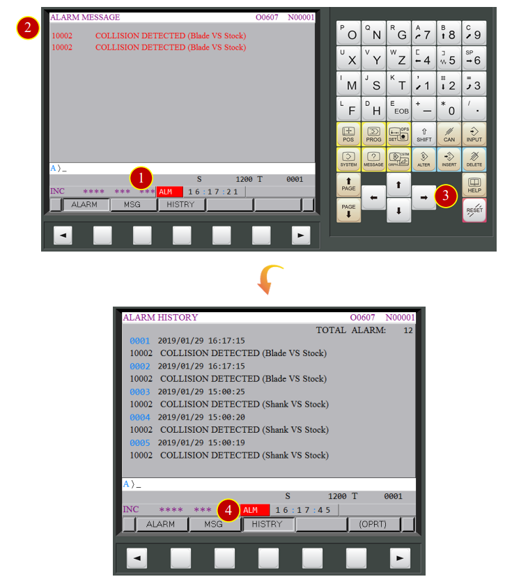
7.5 Machine Alarm
When the machine operation occurs errors, the panel will raise ALARM notification
7.5.1 Release the Alarm
(1) When the “ALM” status on the controller is flashing
(2) Check the alarm number and content, and deal with it according to it
(3) Press【RESET】to clear the alarm after checking the alarm detail
(4) Press【HISTRY】button of【MESSAGE】window to check alarm history
7.5.2 Return to Auto Run Mode
It is necessary to return to Auto Run Mode
when the program is interrupted or the alarm notification shows up
(1) Press【PROG】to return to the program display window
(2) Change to【EDIT】mode
(3) Press【RESET】to set the cursor back to the begging of the program
(4) Select the needed mode
e.g.【AUTO】mode
(5) Make sure the cursor is at the beginning of the program again,
Press【CYCLE START】to Auto Run
文章區塊