
CH7_Machine Basic Operation_Siemens Turning
today
2024-12-02
local_offer
Siemens Turning
visibility
1863
7. Machine Basic Operation
7.1 ZRN Operation
After turn on the machine, return every axis to zero point for building up the reference position as the according of the movement of the coordinate, therefore it can run automatically
7.1.1 Operation Steps
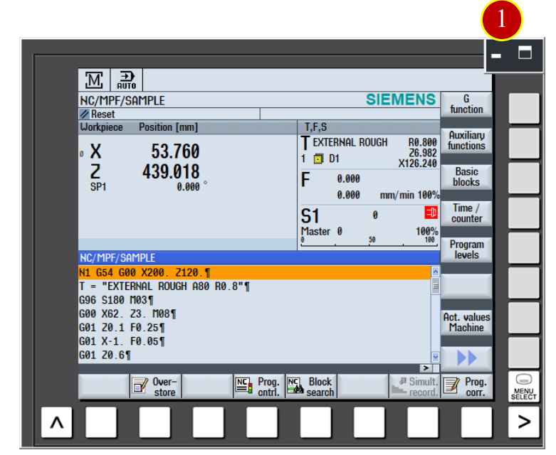
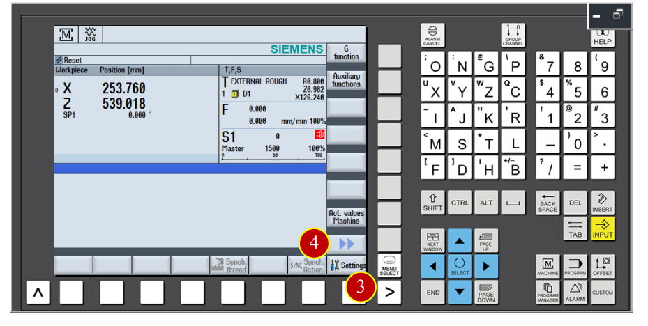
(1) Click the【Maximize】button of [Controller function area]
(2) Click the【Machine】coordinate function button
(3) Check the function buttons of 【Machine】
Work coordinate: Add the coordinate positions of work offset and tool offset
according to the machine coordinate

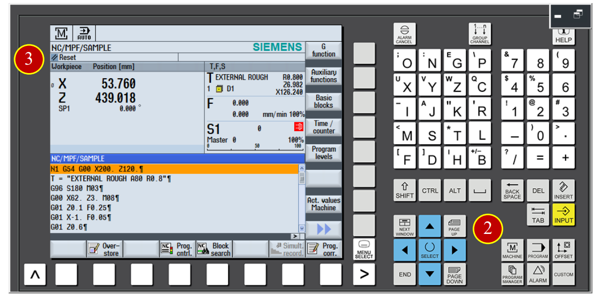
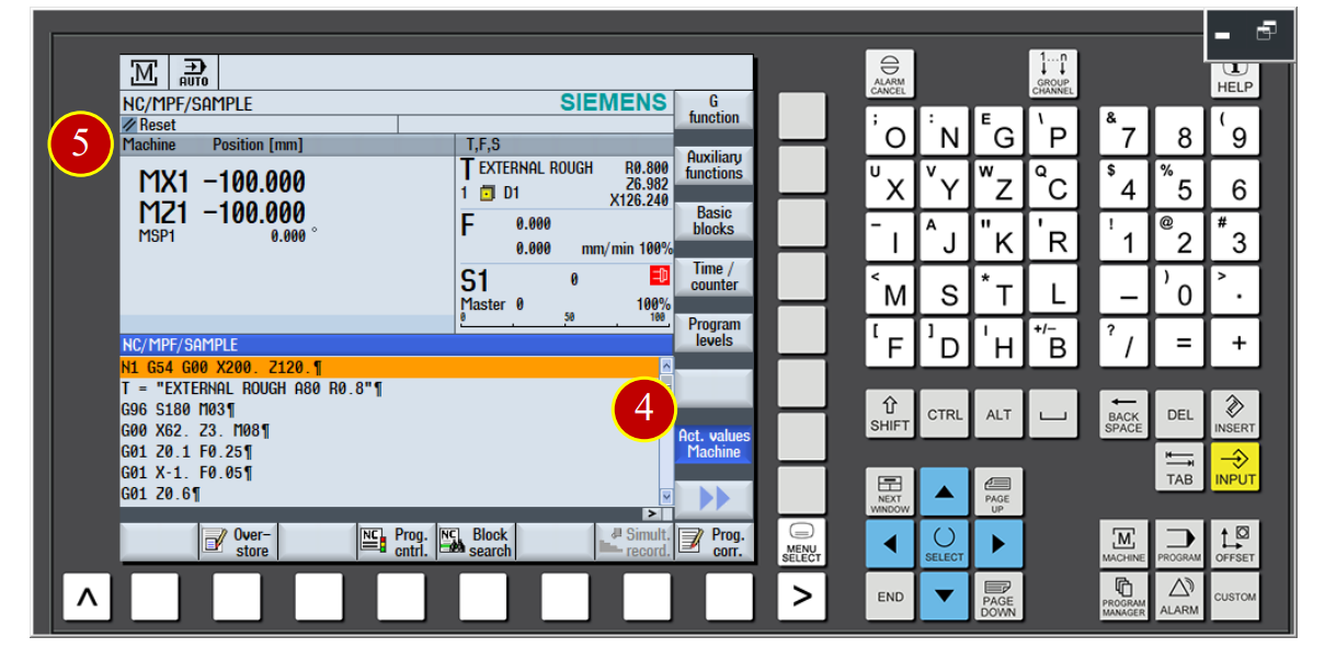
(4) Click the【Actual Value】button of the menu, switch the window to
machine coordinate (Machine) checking window.
(5) Check the machine coordinate value (Machine)
[Work Coordinate (WCS)]:Add work offset and tool offset coordinate position
with the machine coordinate.
[Machine Coordinate(MCS)]: Use machine zero point as the coordinate position of
Reference zero point.
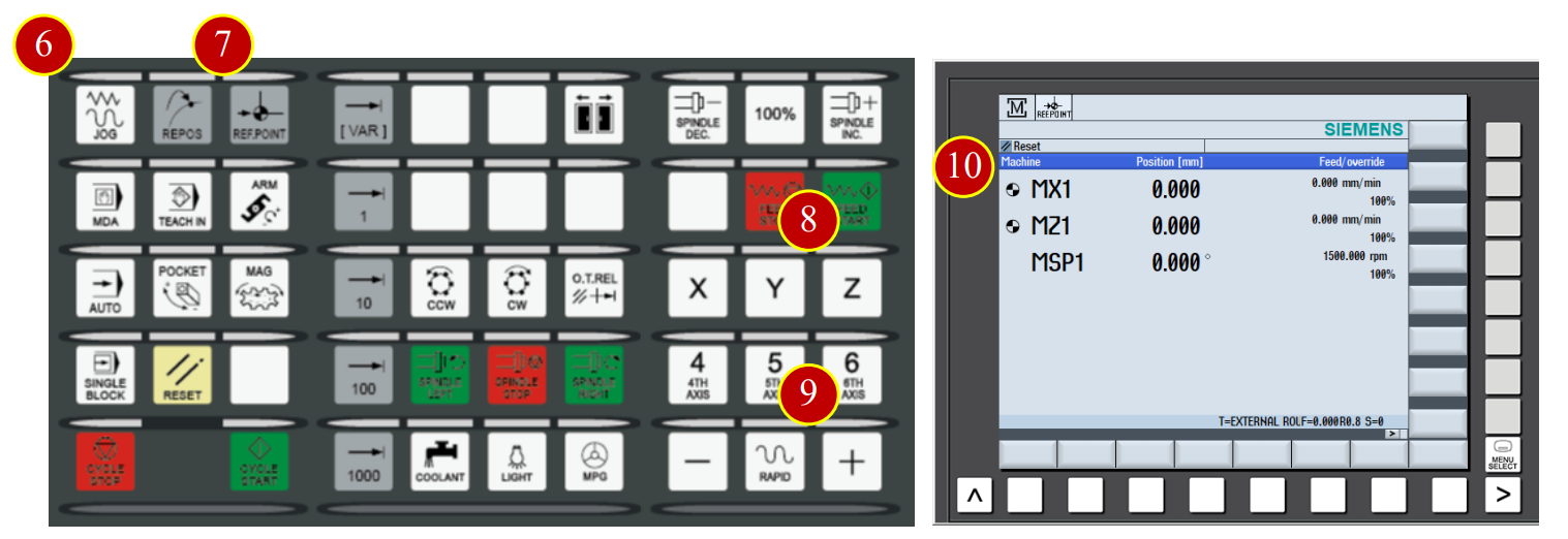
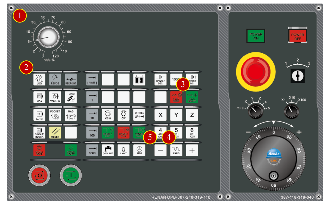
(6) Click the [JOG] mode of the controller panel
(7) When the light of [JOG mode] is on, click [REF.POINT mode]
(Return to Reference Point)
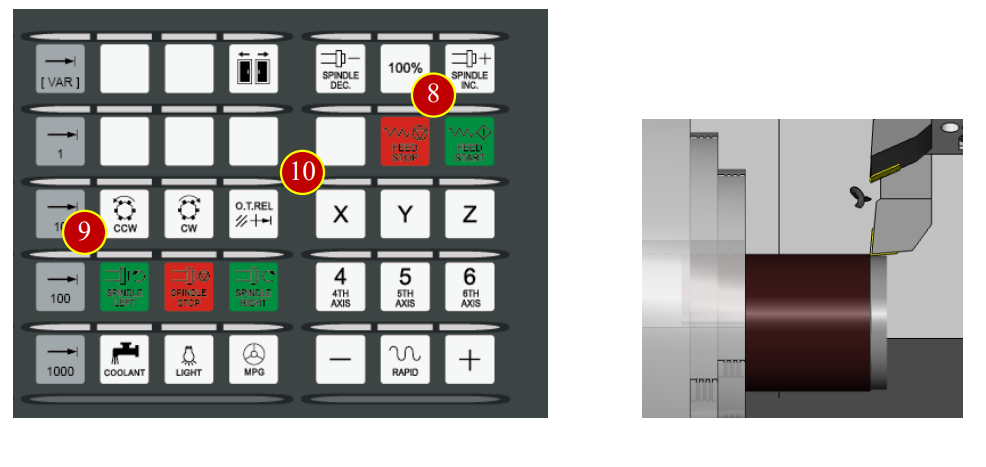
(8) Click [Z] button
(9) Click [+] button, axis return to the zero point of Z axis with rapidly speed
(10) When the machine coordinate of Z axis is 0, it will show up the symbol,
it means zero point returning of Z axis is done.
(11) Continue to execute ZRN movement of X axis.
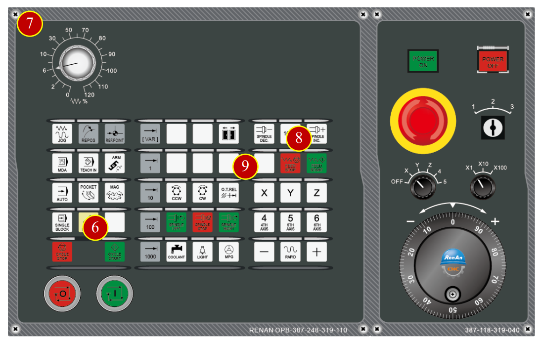
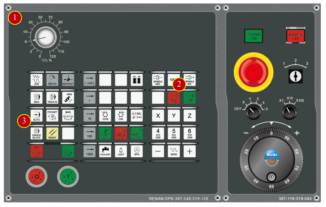
7.2 Method of Tool Movement
6.2.1 Rapid Movement
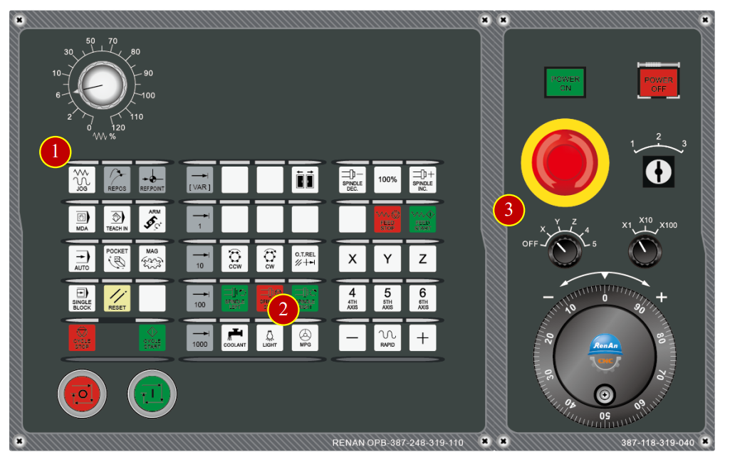
(1) Before manual operation, switch [cutting feed adjust button] to 30% position instead of 100% position
(2) Switch the mode to【JOG】mode on the controller panel
(3) Click【FEED START】to start the cutting feed function
(4) Click【RAPID】button to switch to rapid movement mode
(5) Use axial button to move the tool rapidly to the position about 50mm from the Workpiece
*Caution: For the safety, the system will always exit the rapid movement mode every time release the or button, click【RAPID】to reenter the rapid movement mode
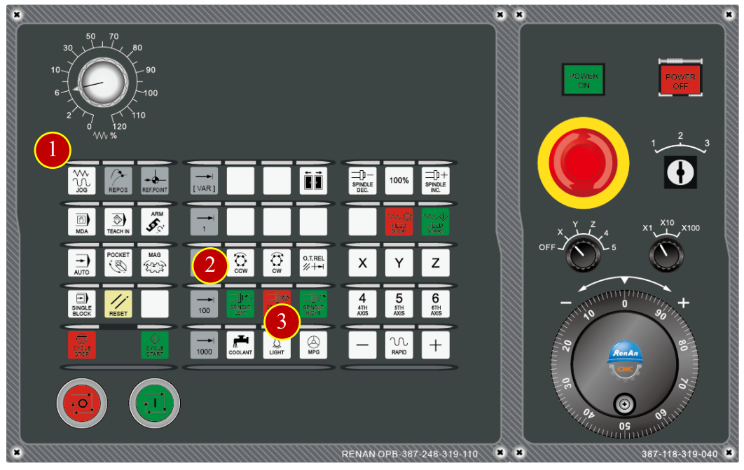
7.2.2 Cutting Feed [JOG Mode] (Feed per Minute Used)
(1) Click the【JOG】button on the controller panel, switch to JOG mode
(2) Switch the【Edit Key】to level 3, Unlock the tool data
(3) Click【 】page switching function button
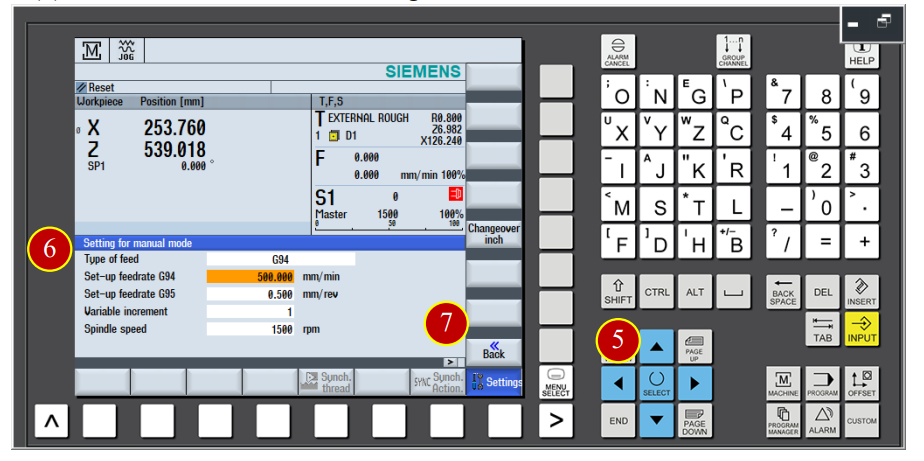
(4) Click 【Setting】, switch to [manual working setting] page
(5) Click 【SELECT】to set the feeding method to G94
(6) Set the feeding value setting to 500mm/ min
(7) Click 【Back】to finish setting
(8) Click the 【FEED START】button on the controller panel to start the cutting feed function
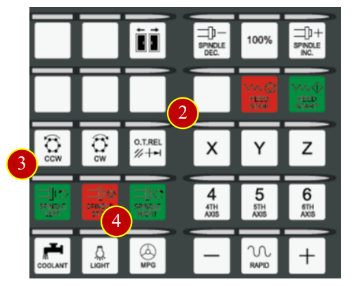
(9) Click 【SPINDLE LEFT】button to make the spindle rotate forward
(10) Use axial movement button to move the tool and cut the material
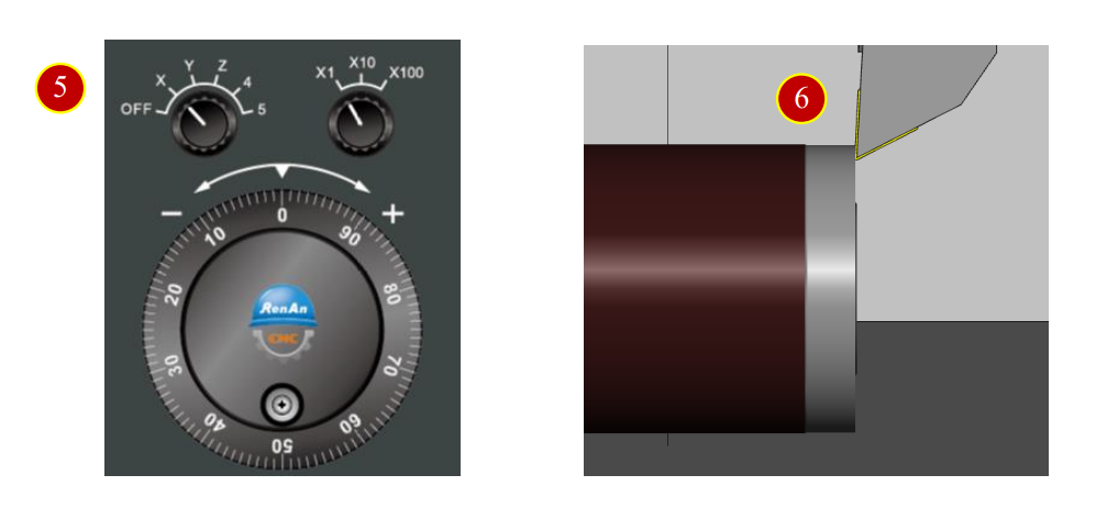
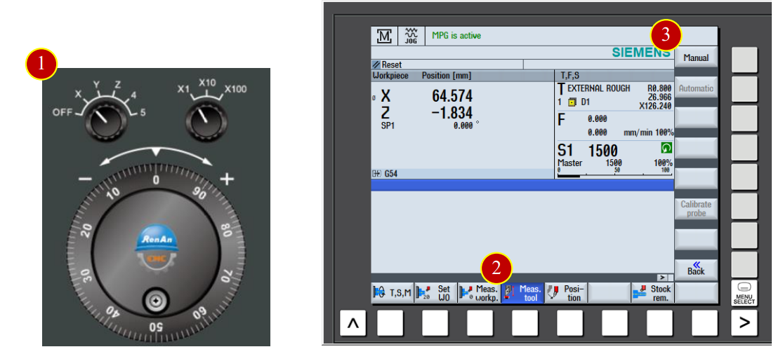
7.2.3 Hand Wheel Movement
(1) Click the 【JOG】button on the controller panel, switch the mode to manual JOG mode
(2) Click the 【MPG】button to turn on the hand wheel
(3) Use hand wheel to move the tool to the left side of the workpiece
When the tool is about 15mm far from the workpiece, hand wheel feed x100
When the tool is under 15mm from the workpiece , hand wheel feed x10
(4) When the tool touch the workpiece and start cutting, slowdown and keep moving forward
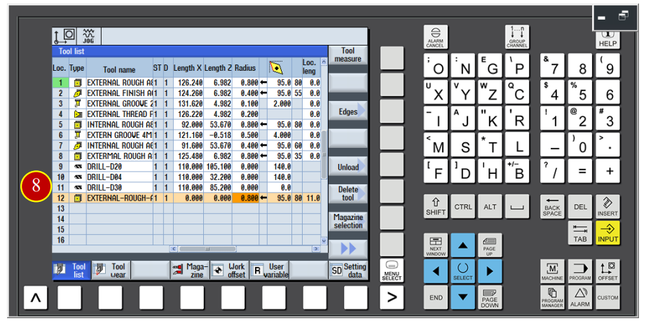
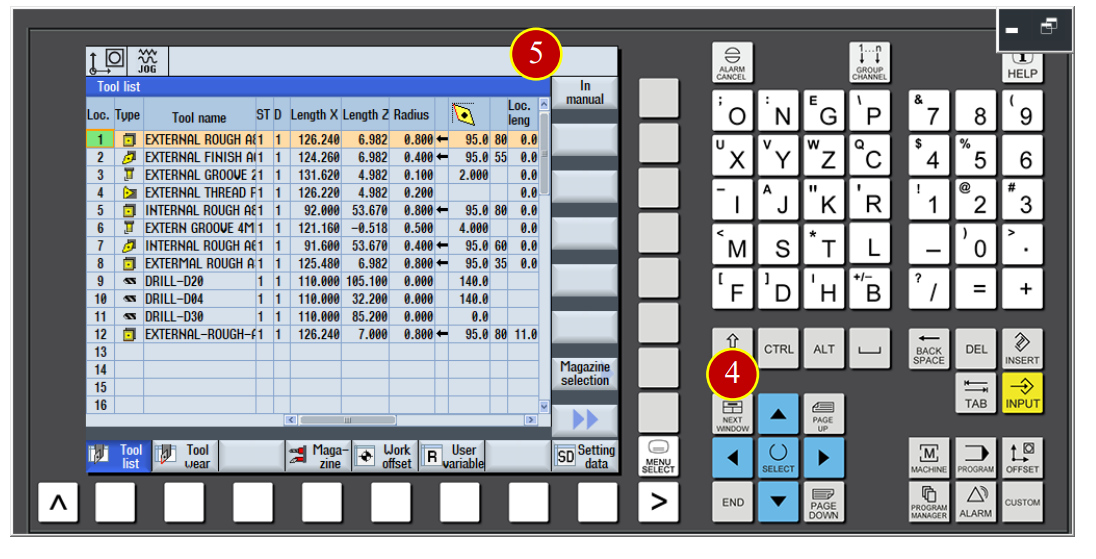
7.3 Add new tool in the controller panel
e.g. Add new tool data [External-Rough-A80-R0.8] at No.12 tool position in the controller panel
7.3.1 Add new tool in the controller panel
(1) Click【JOG】button in the controller panel
(2) Switch the 【Program Editing Lock】to level 3, release the lock of tool list protection
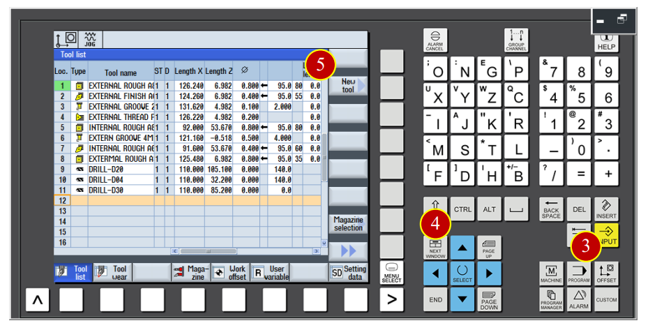
(3) Click【OFFSET】button in category function display buttons to switch to the [Tool Data] page
(4) Use arrow keys to move the cursor to the No.12 tool position
(5) Click【New Tool】option to enter the adding tool page
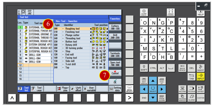
(6) Click【Roughing Tool】
(7) Click【OK】to add No.12 tool
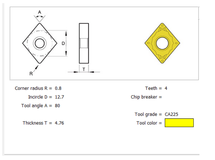
(8) Key in the basic tool data, tool name [External-Rough-A80-R0.8]
Radius=R0.8 (Accroding to the radius of tool nose)
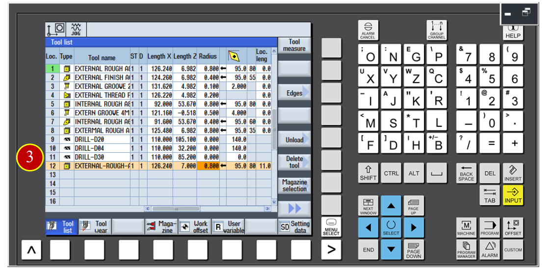
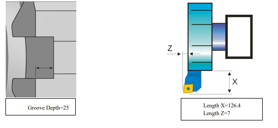
7.3.2 Tool Data Setting
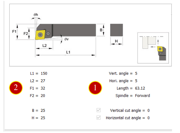
(1) Length X=126.24 (Single length 63.12)*2= 126.24
(2) Length Z=7.000 (Width of tool holder=32)-(Groove Depth=25)=Length 7
(3) Finish the tool length setting
7.4 Work Coordinate Setting and Tool Offset setting
When changing to a new work, the data needs to be reset accroding to the
Size of the work to add the correct work shift coordinate (X Axis and Z Axis)
After installing the tool, it needs to set the tool geometry offset value in order to
Move and cut correctly when executing the CNC program.
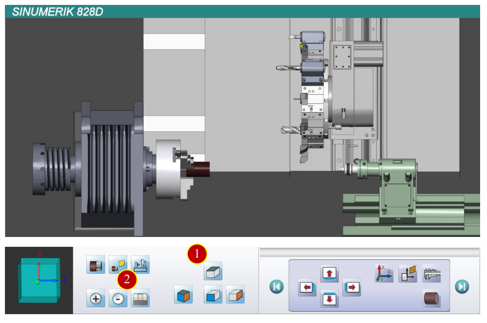
7.4.1 View Adjustment Operation
Adjust the view to the proper size and angle
(1) Click【Top View】button of View Tool Bar
(2) Click【Shell】to hide the machine shell
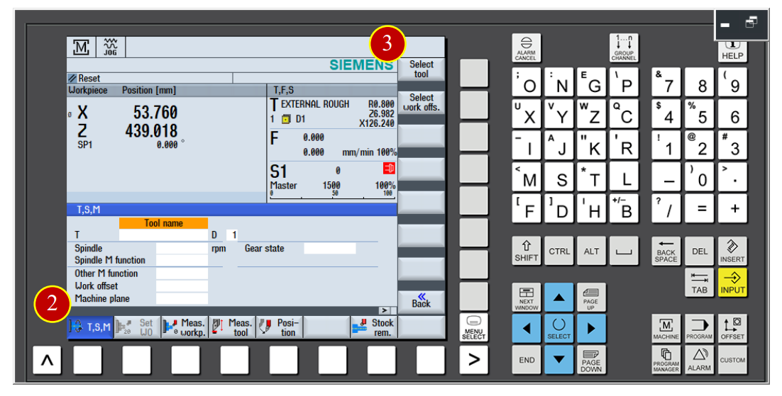
7.4.2 Change tool and move the tool close to the workpiece
(1) Click the【JOG】button in the controller panel
(2) Click【T,S,M】button
(3) Click【Select Tool】function swtich to the [Tool Data List] page
(4) Use arrow keys to move the cursor to the No.1 tool position
(5) Click【In manual】function to move the tool data list back to the [T,S,M] page
(6) Click the【CYCLE START】button to change the tool
(7) Before the manual operation, switch the【Feed Rate】override knob to 50%
(or 25%) Position (Can not be at the 100% position)
(8) Click【FEED START】button, start the feeding function, clear the feeding lock
(9) Use the【Axial Movement】button to move the tool rapidly, and reach the
Position about 50mm from the work
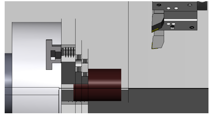
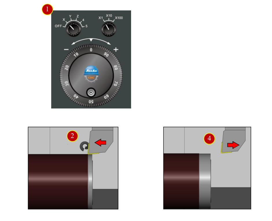
7.4.3 Cutting the Reference Line (Face)
(1) Click the【JOG】button in controller panel
(2) Click【Spindle Left】to start the rotation
(3) Click【MPG】to start the hand wheel
(4) Move the tool to the work with the hand wheel to cut the end face lightly for about 0.5mm
(5) Push the tool downward (-X Direction) to cut the work for about 15mm
(6) Remove the tool rightward (+Z direction) (About 1mm apart from the work)
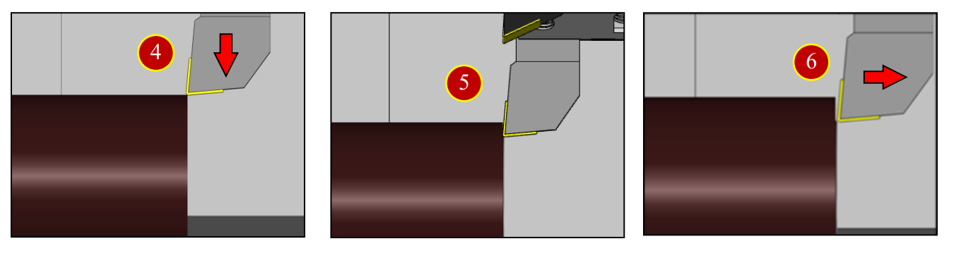
7.4.4 Cutting the Reference Line (Outer Diameter)
(1) Rotate the hand wheel to cut the work external diameter slightly (depth= about 0.5mm)
(2) Cut 15mm deeper leftward to the (-Z) direction
(3) Remove the tool upward about 1mm upward to the (+X) position
(4) Remove the tool rightward to the (+Z) position to leave the work
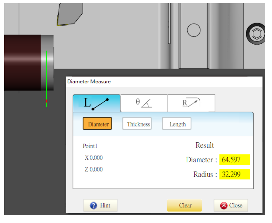
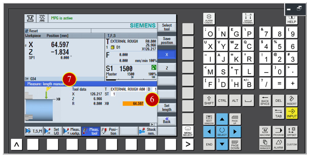
7.4.5 External Diameter Measurement
(1) When the tool leave the work, click【Spindle Stop】button
(2) Click【Diameter Measure】button to open the measurement assisted tool
(3) Right click with the mouse to choose the cut external diameter to get the diameter=64.597
(4) Click【Close】to close the window
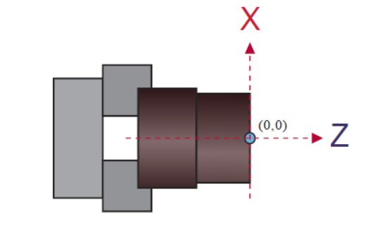
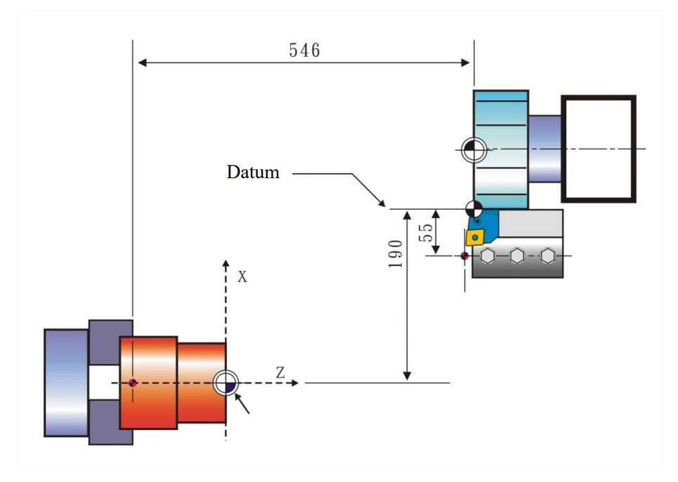
7.4.6 Workpiece Coordinate and Reference Base Point Setting Reference Base Value definition:
(1) The shifted distance between the turret and the jaw is reference base value
(2) Machine execute every category of program cutting and positioning movement based on the value
Base Point Definition of the Example:
(3) X Axis, use the outside edge of turret and the bottom of the tool carriage as the base reference position
(4) Z Axis, use the left side end face of the turret as the base reference position
The Offset Method:
(5) The value from the center of internal groove carriage to the center of the spindle is fixed
(6) The geometry offset value of the drill, taps and the mills is fixed as 110, no need to offset
(The distance between the turret to the center of internal diameter hole is 55mm,
55*2 X=110)
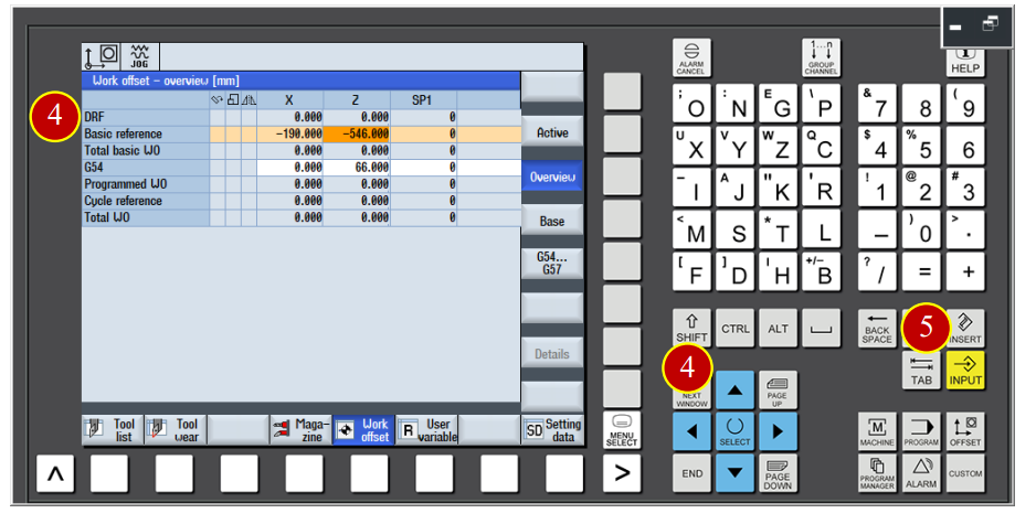
7.4.7 Base Reference Setting
(1) Click【OFFSET】
(2) Click【Work Offset】to open the zero point offset window
(3) Click【Overview】to switch to the overview window
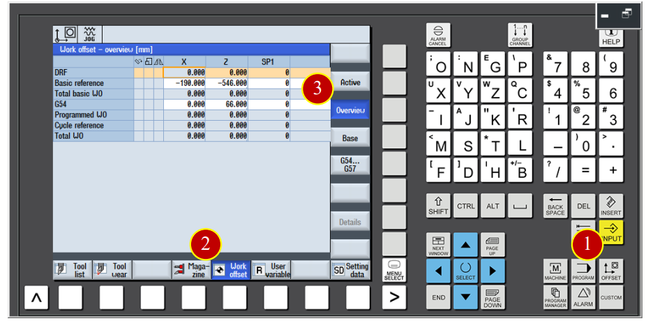
(4) Use arrow keys to move the cursor to the base reference X column, key in -190 and click【INPUT】(-400+ Turret radius 210= -190)
(5) Move cursor to the base reference Z column, key in -546 and click【INPUT】
(-600+ Jaws width 54= -546)
7.4.8 Work Coordinate G54 Setting
Take No.2 External Finishing Tool as the example to explain the setting method
(1) Open [JOG] mode and change tool number to No.2 tool
(2) Use Axial direction movement button to move the tool rapidly to the position about 50mm apart from the work
(3) Click【Left】to start the spindle rotation
(4) Click【MPG】to start handwheel function
(5) Rotate【Handwheel】to move the tool about 8MM below the diameter of work face
(6) Keep moving leftward to –Z direction, and move backward 0.02mm to +Z direction when the tool touch the work face lightly
Note: When chips and cracks appear, it means work is touched
(7) Click the【Meas. workp】button in the controller panel, enter the work coordinate setting window
(8) Use arrow keys and 【SELECT】button to set the zero offset value as G54
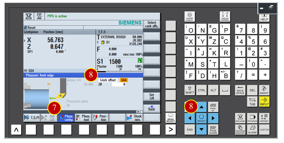
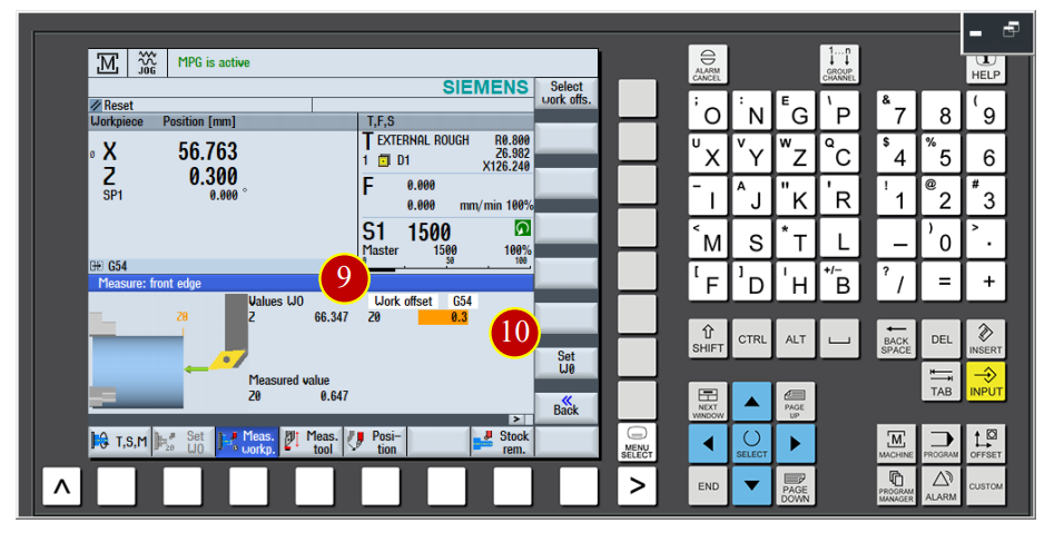
(9) Move cursor to the Z0 column and key in 0.3
(Actual zero point is 0.3mm ahead the face.)
(10) Click【Set W0】function button to get the zero point value Z=66.347
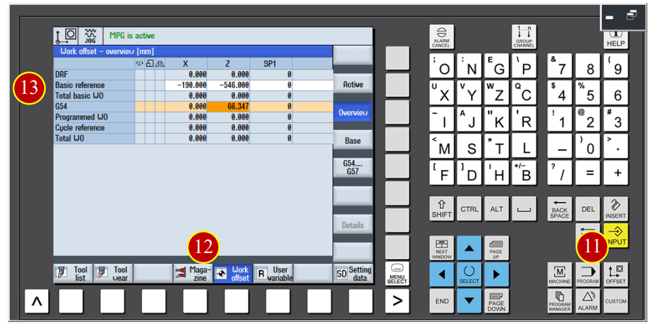
(11) Click【OFFSET】
(12) Click【Work Offset】to open the zero point offset page, the G54 Z value is changed to 66.347
(13) Move the cursor to the G54 X column, key in 0 and click【INPUT】
7.4.9 Tool geometry Offset Setting (Each Z Axis offset)
Set each geometry offset value. Take No.1 tool as example to explain the offset method.
(1) Use the hand wheel to move the tool, touch the base plan slightly with the tool
(Through the end face that is cut by the specify master tool)
(When the chips appear, it means the work is cut, stop moving forward immediately)
(2) Click【Meas. Tool】function
(3) Click【Manul】function and switch to measure page
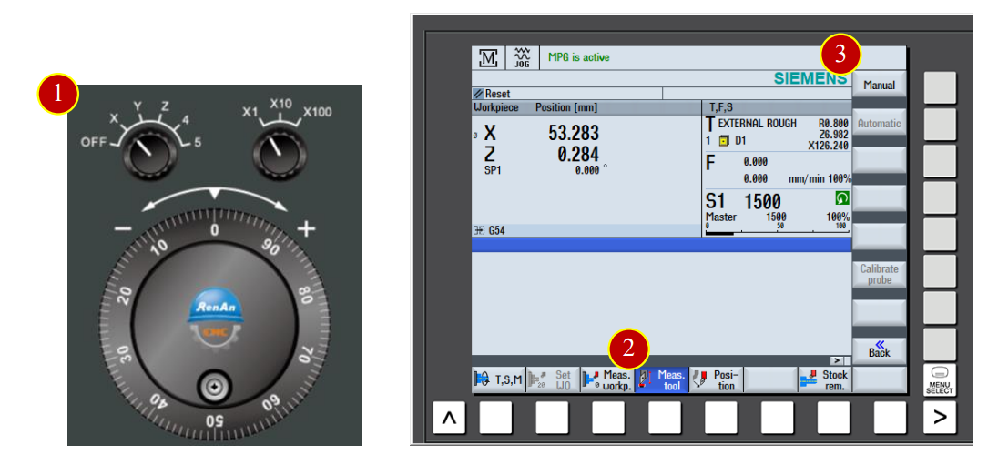
(4) Click【Z】function to switch to Z Tool Axis measure page
(5) Move the cursor to Z0 column and key in 0.3
(6) Click【Set Length】function button and measure the length
(7) When the tool data value show up as Z=6.966, it means the No.1 tool length
Z Axis Offset Setting is done
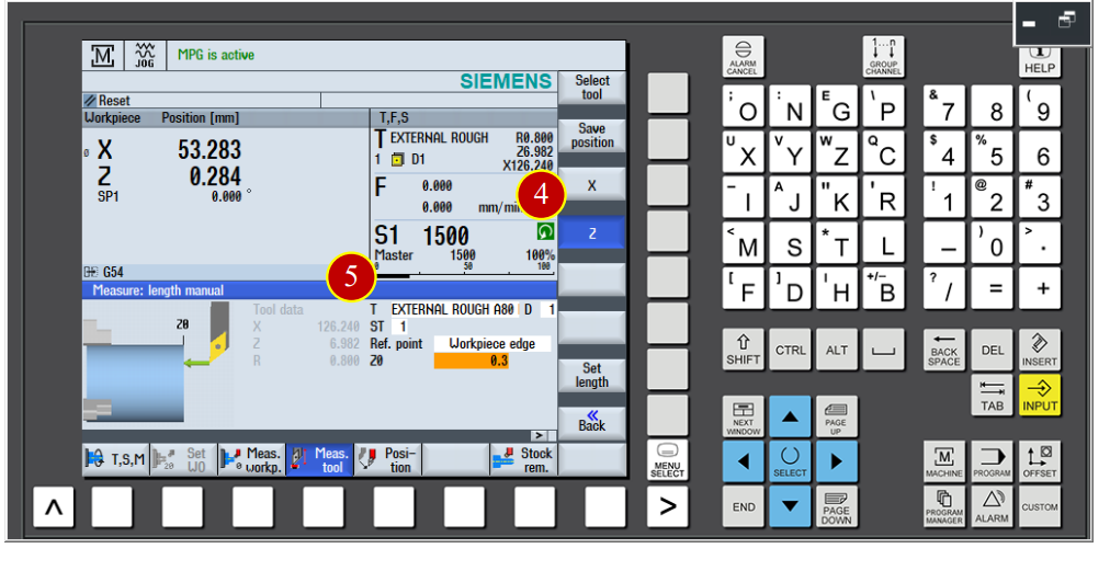
7.4.10 Tool geometry Offset Setting (Each X Axis offset)
(1) Use the hand wheel to move the tool, touch the work from the outside diameter of right end face slightly with it
(2) Click【Meas. Tool】function
(3) Click【Manul】function and switch to measure mode page
(4) Click【X】function to switch to X Tool Axis measure page
(5) Key in the measured diameter value 64.597 in the X0 column
(6) Click【Set Length】function button to measure the tool length
(7) When the tool data value show up X=126.217 it means the X axis tool offset of No.1 tool is finished
7.5 Auto Run Program
Use the auto run function to make controller execute NC code
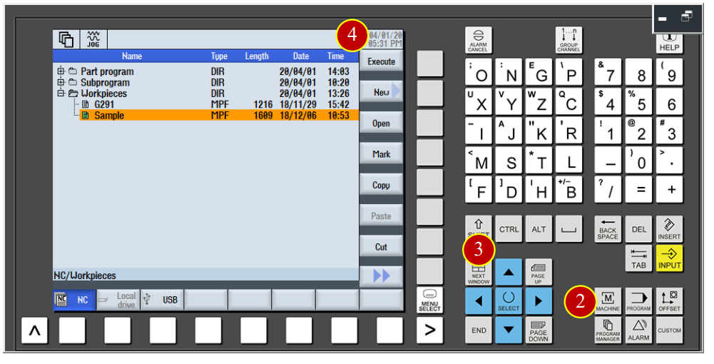
7.5.1 Choose the CNC machining steps
(1) Click the【AUTO】button of the controler panel to switch to the [AUTO] mode
(2) Click【PROGRAM MANAGER】
(3) Use arrow keys to move the cursor to the position Sample.MPF in program
(4) Click【Execute】button to install the Sample.MPF program, and switch to the
Machine machining area automaticlly.

7.5.2 Auto run buttons Check
(1) Before the program run automaticlly, switch【Feed Rate】
override knob to the 30%
(2) Click【FEED START】to start the feeding rate function
(3) Click【SINGLE BLOCK】one block execution button
(success when the light is on)
7.5.3 Auto Run Steps Operation Function Adjustment
(1) Click【Prog. Cntrl.】function
(2) Click【Select】to select [RGO] and [M01] options
(3) Click to switch the option page
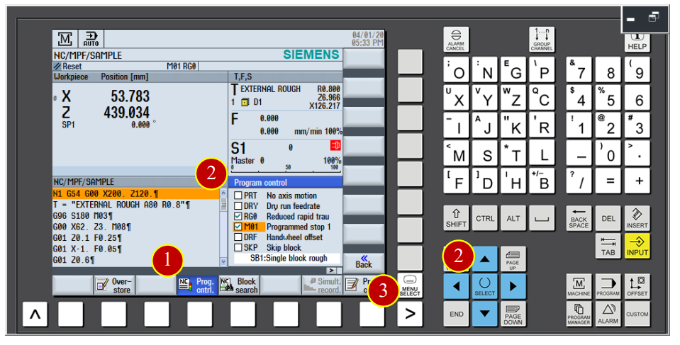
(4) Click【SETTING】to enter the auto run setting page
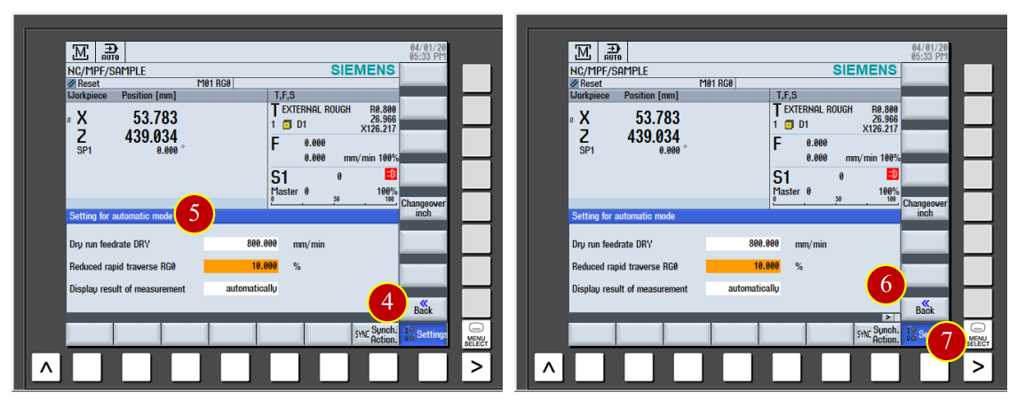
(5) Key in 800.000 in the [DRY] column
Key in 10.000 in the [PG0] column
(6) Click【BACK】
(7) Click to back to the option page
7.5.4 Program Execution
(1) Click the【CYCLE START】button in the controller panel to execute the program
(2) Pay attention on the movement of tool, click【CYCLE STOP】button immidiately
when the tool is close to the work (about 50mm)
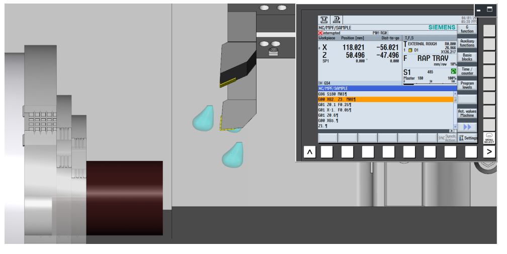
(3) Check if the position of tool and workpiece is match to the size of program coordinate
e.g. Program Realative Coordinate Z= 50.496, tool nose is about 50mm apart from work by
vision
(4) Click【CYCLE START】to continue the program execution
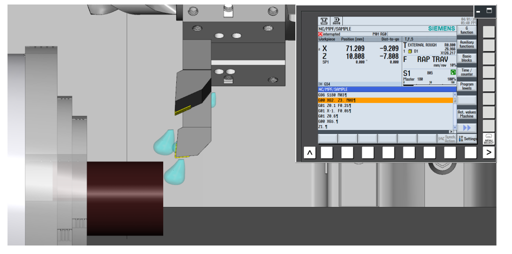
(5) When the tool is closer to the work (about 10mm apart), click【CYCLE STOP】to stop the Feeding
(6) Switch【Feed Rate】override knob to [80%] position
(7) Make sure the position of tool and work is match to the program coordinate value
(a) *Caution: During the commissioning period, as long as the tool is close to the work, make Sure the [RG0] column is selected in order to slow down the speed of rapid movement for the Safety.
(b) Anytime when feel something wrong, click the【CYCLE STOP】button immidiately to recheck again.
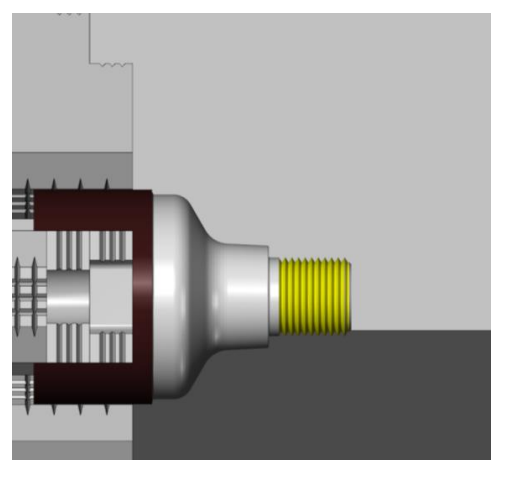
(8) Keep cutting until it’s done
The finished product:
7.6 Machine Alarm
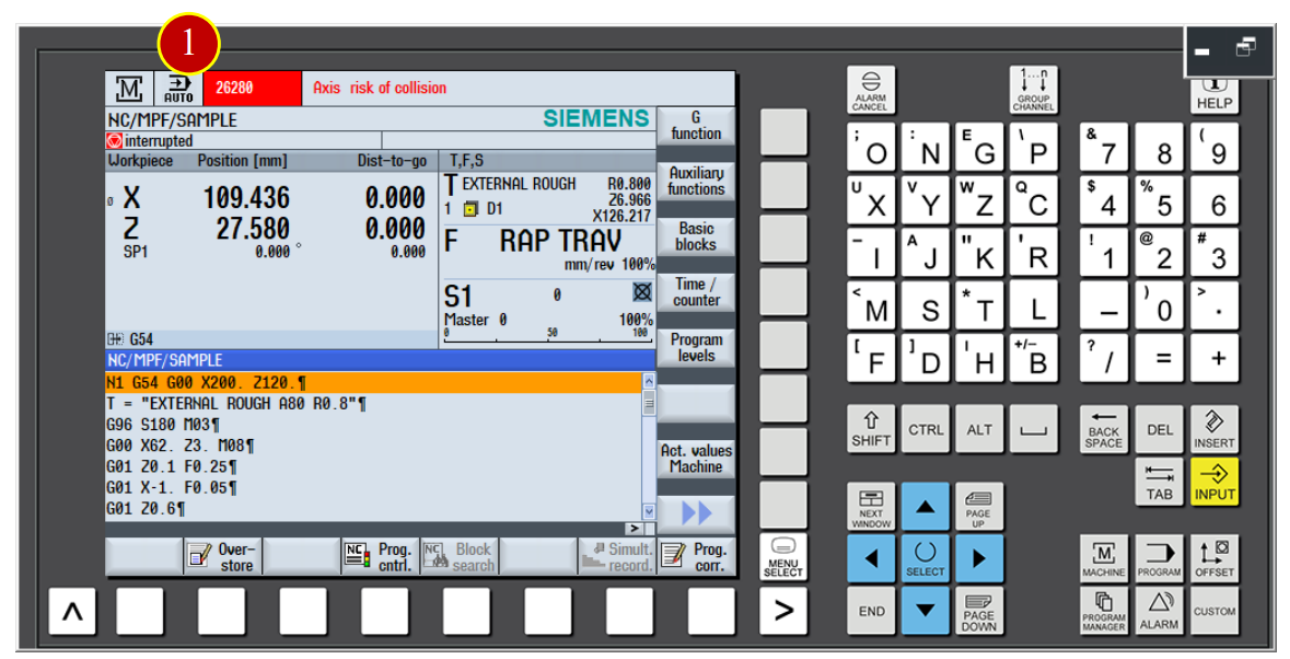
When the error occurs, alarm will show up on the controller panel
7.6.1 Check and ckear alarm
(1) When the controller panel is showing “ALM”
(2) Check the alarming code and content, then correct the error according to the content
(3) Press【RESET】after the correction of errors to clear the alarm

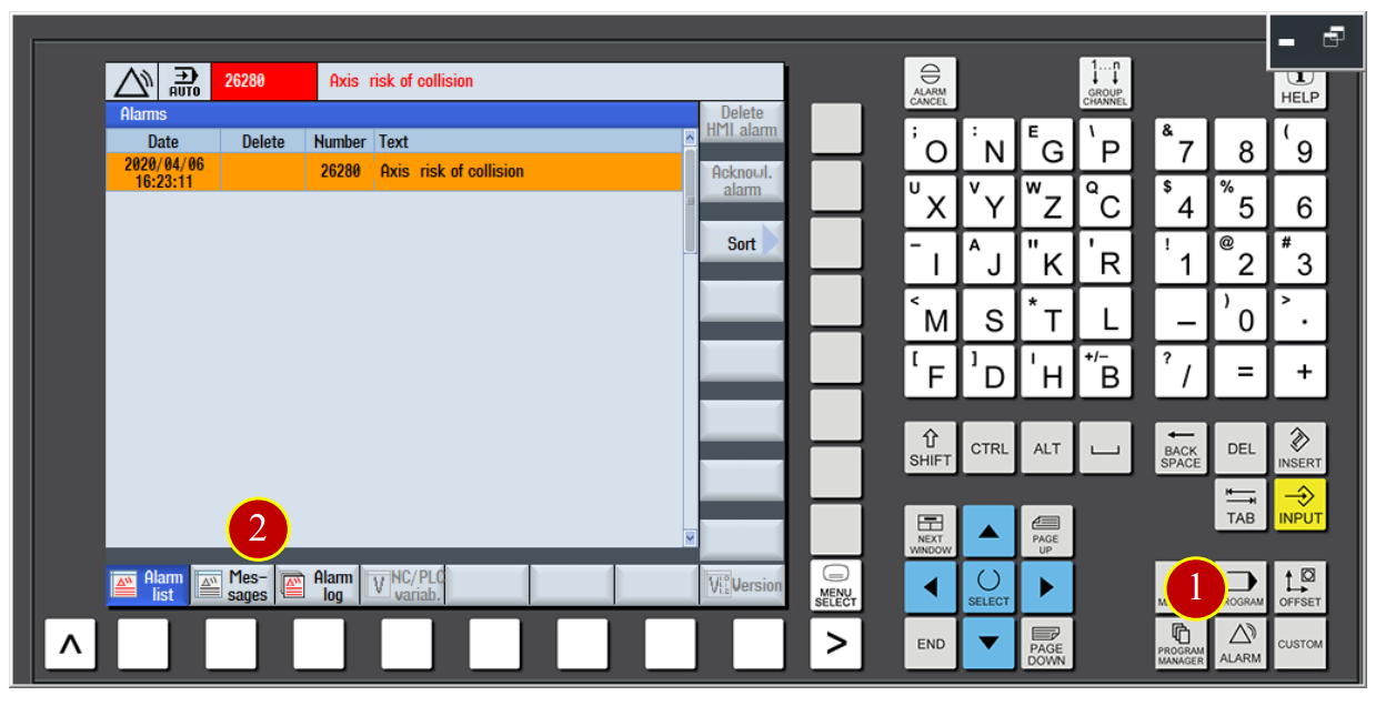
7.6.2 Check History ALARM information
(1) Press【ALARM】button
(2) Click【Alarm log】option to check the history information
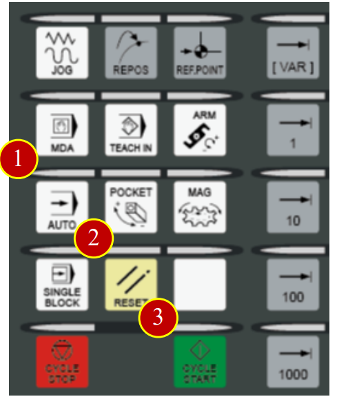
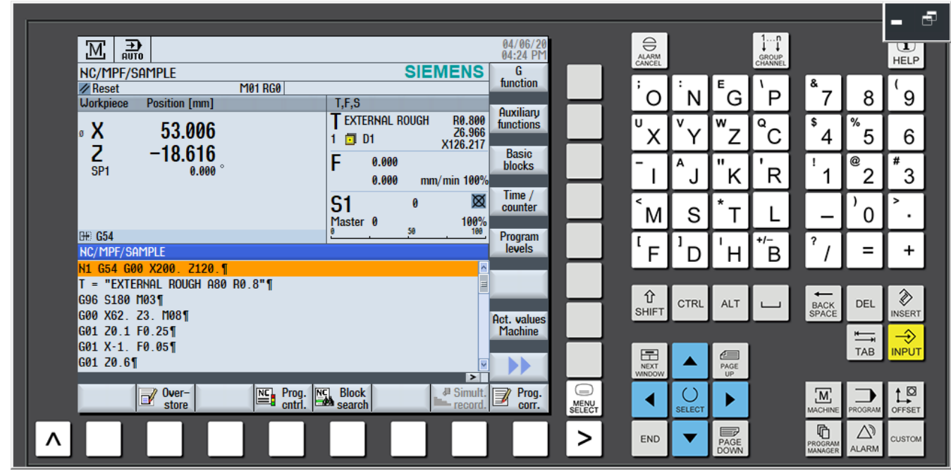
7.6.3 Back to AUTO Run
When the program is interrupted, or trying to go back to AUTO Run window from the alarm notifition
(1) Click【AUTO】button on the controller panel
(2) Click【RESET】and move the cursor back to the beginning of the program
(3) Make sure the cursor is at the begginging and press【CYCLE START】to auto-run
文章區塊