
CH7_Machine Basic Operation_Siemens Milling
today
2025-01-07
local_offer
Siemens Milling
visibility
1982
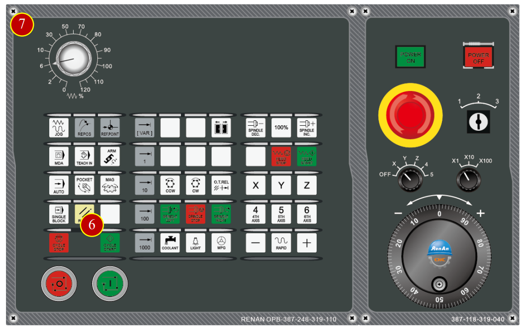
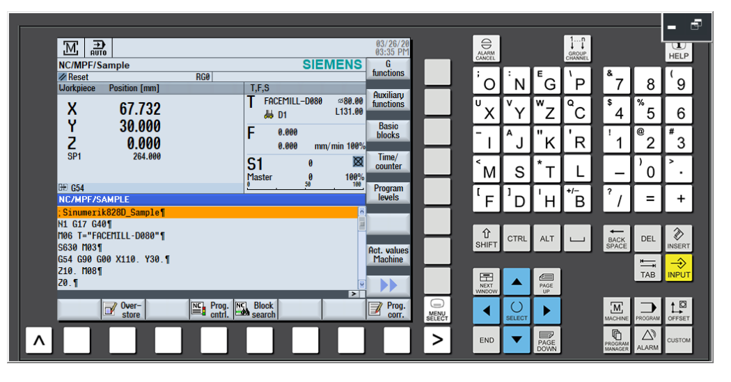
7. Machine Basic Operation
7.1 ZRN Operation
After turn on the machine, return every axis to zero point for building up the reference position as the according of the movement of the coordinate, therefore it can run automatically
7.1.1 Operation Steps
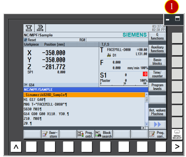
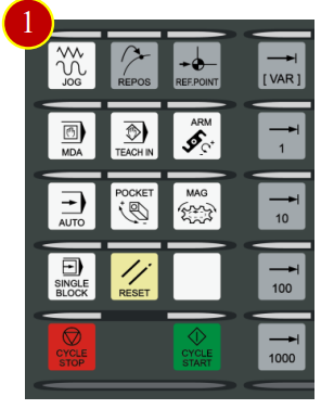
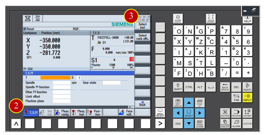
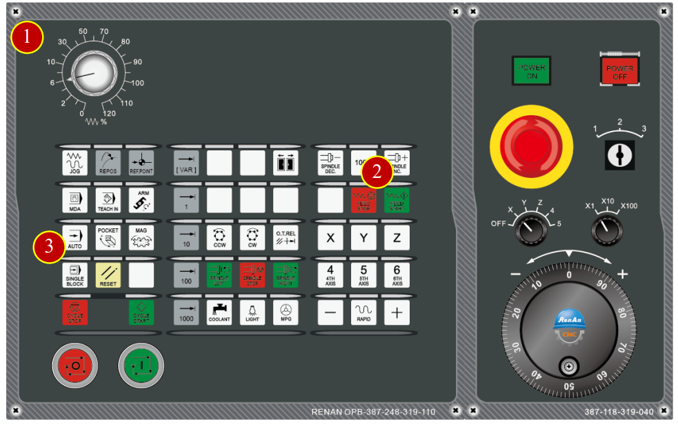
(1) Click the【Maximize】button of [Controller function area]
(2) Click the【Machine】coordinate function button
(3) Check the Work coordinate: Add the coordinate positions of work offset and tool offset
according to the machine coordinate

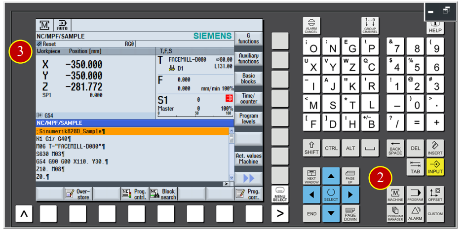
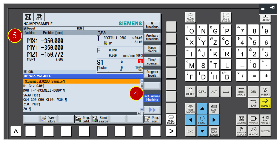
(4) Click the【Actual Value MCS】button of the menu, switch the window to
machine coordinate (Machine) checking window.
(5) Check the machine coordinate value (Machine)
[Work Coordinate (WCS)]:Add work offset and tool offset coordinate position with
The machine coordinate.
[Machine Coordinate(MCS)]: Use machine zero point as the coordinate position of
Reference zero point.
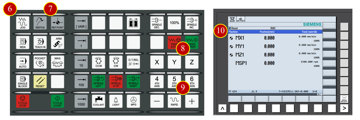
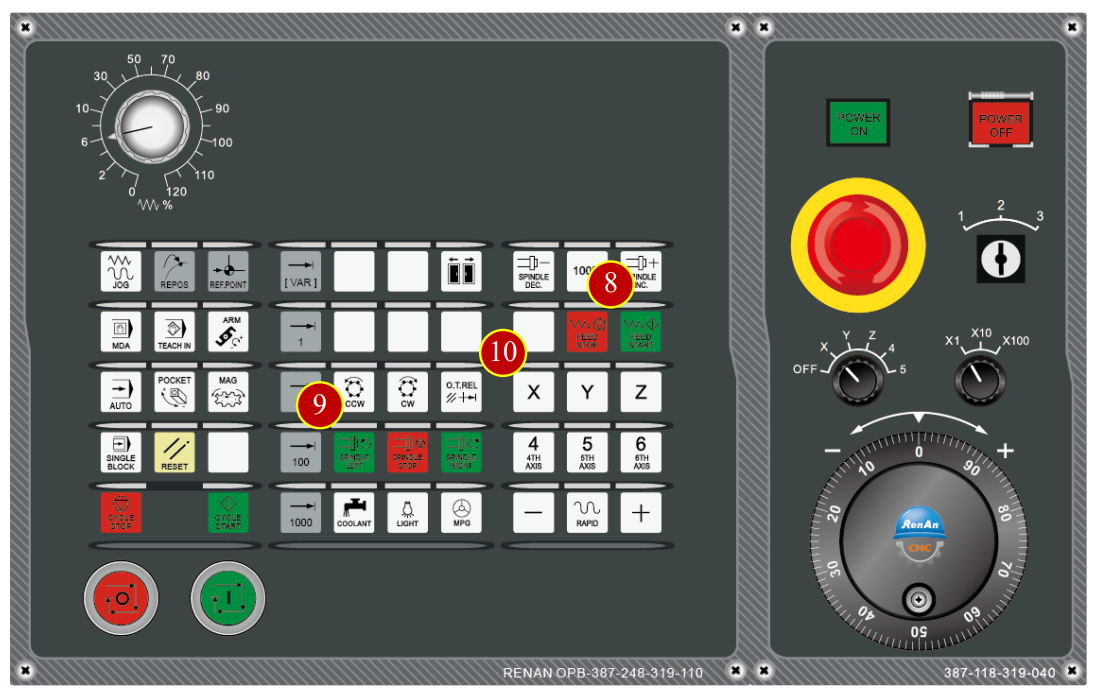
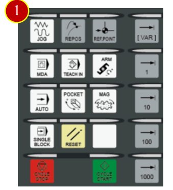
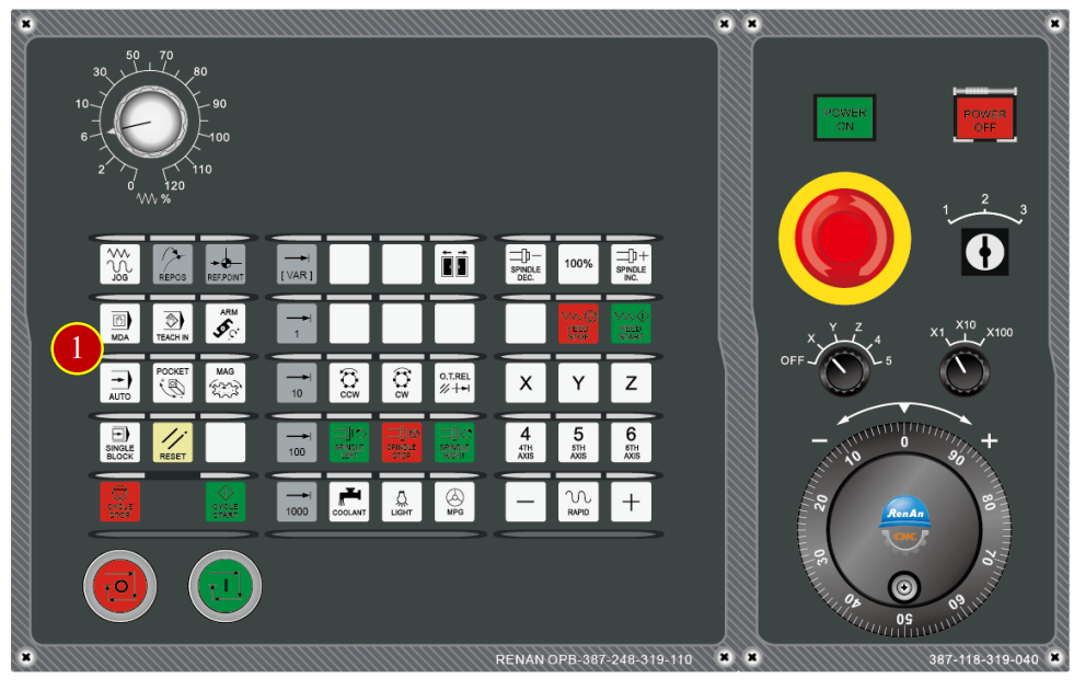
(6) Click the [JOG] mode of the controller panel
(7) When the light of [JOG mode] is on, click [REF.POINT mode]
(Return to Reference Point)
(8) Click [Z] button
(9) Click [+] button, axis return to the zero point of Z axis with rapidly speed
(10) When the machine coordinate of Z axis is 0, it will show up the symbol,
it means zero point returning of Z axis is done.
(11) Continue to execute the zero point returning movement of X and Y Axis
7.2 Method of Tool Movement
7.2.1 Rapid Movement
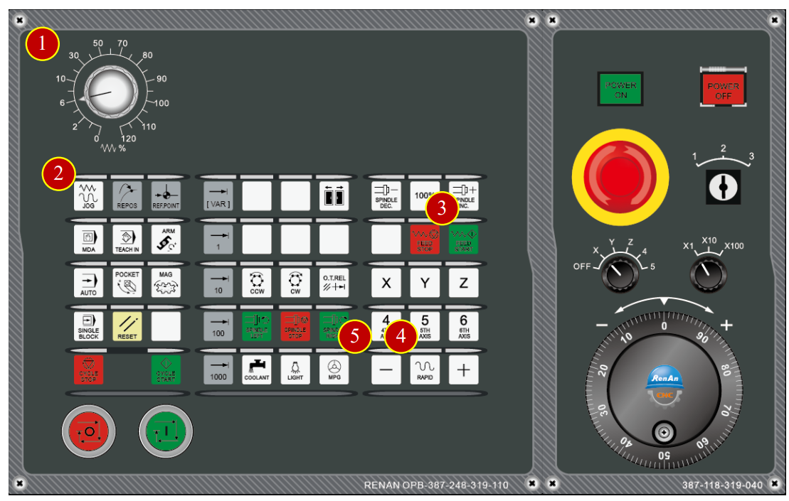
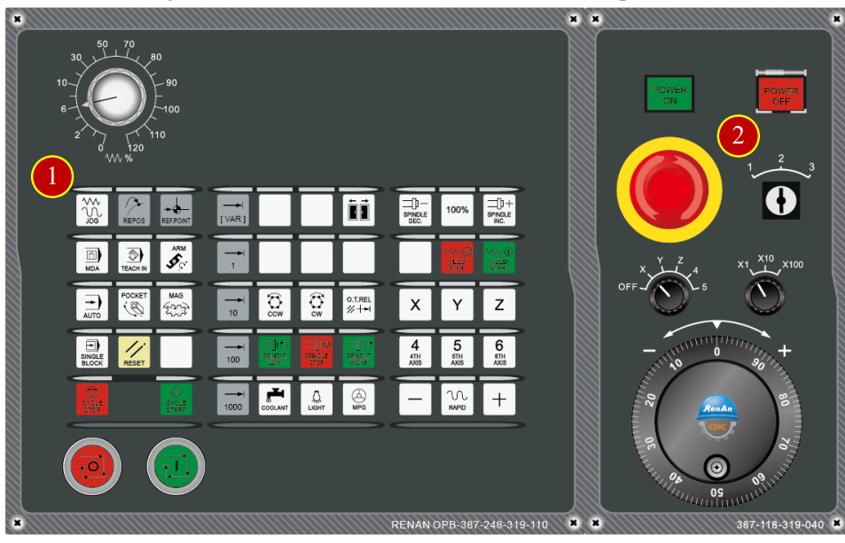
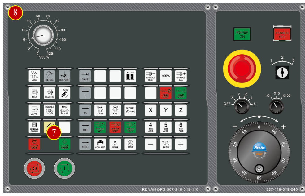
(1) Before manual operation, switch [Feed rate adjust button] to 30% position
instead of 100% position
(2) Switch the mode to【JOG】mode on the controller panel
(3) Click【FEED START】to start the cutting feed function
(4) Click【RAPID】button to switch to rapid movement mode
(5) Use axial button to move the tool rapidly to the position about 50mm from the Workpiece
*Caution: For the safety, every time release the or button the system will
always exit the rapid movement mode, click【RAPID】to reenter the rapid movement mode
7.2.2 Cutting Feed [JOG Mode] ( mm/min)
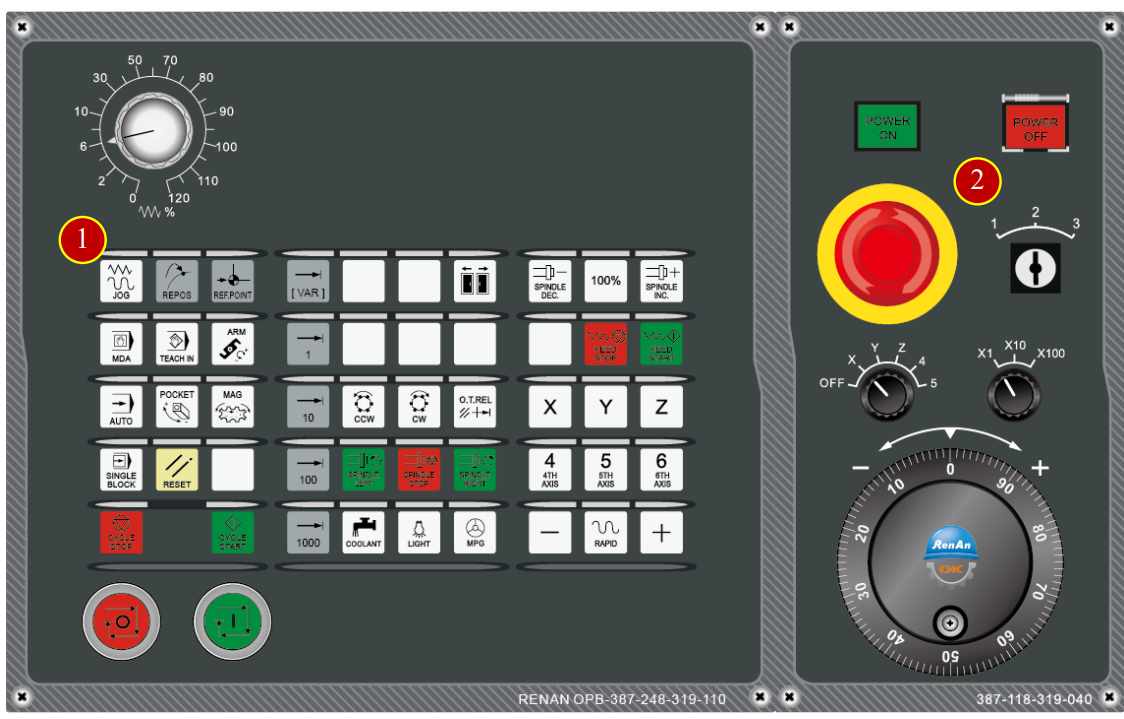
(1) Click the【JOG】button on the controller panel, switch to JOG mode
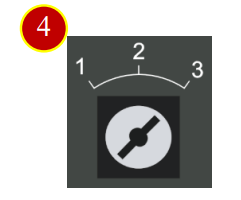
(2) Switch the 【Program Lock】to level 3, Unlock the Tool Data protection
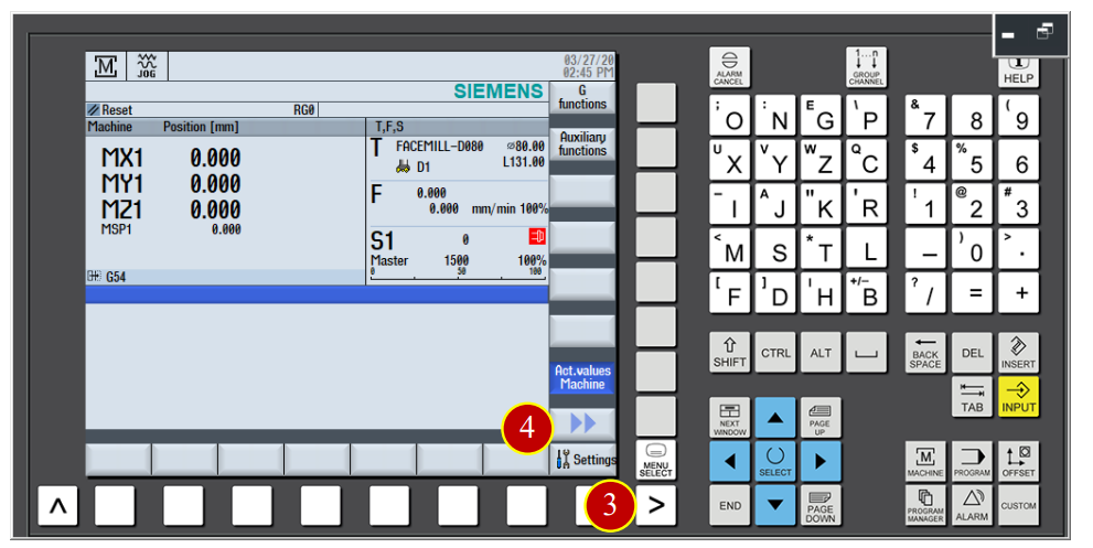
(3) Click【 】page switching function button
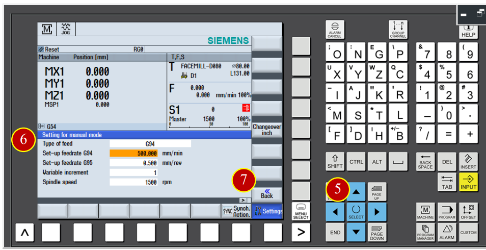
(4) Click 【Setting】, switch to [manual working setting] page
(5) Click 【SELECT】to set the feeding method to G94
(6) Set the feeding value setting to 500mm/ min
(7) Click 【Back】to finish setting
(8) Click the【FEED START】button on the controller panel to start the cutting feed function
(9) Click【SPINDLE LEFT】button to make the spindle rotate forward
(10) Use axial button to move the tool and cut the material
7.2.3 Hand Wheel Movement
(1) Click the 【JOG】button on the controller panel, switch the mode to manual JOG mode
(2) Click the 【MPG】button to turn on the hand wheel
(3) Use hand wheel to move the tool to the right side of the workpiece
When the tool is about 15mm far from the workpiece, hand wheel feed x100
When the tool is under 15mm from the workpiece , hand wheel feed x10
(4) When the tool touch the workpiece and start cutting, slowdown and keep moving forward to cut

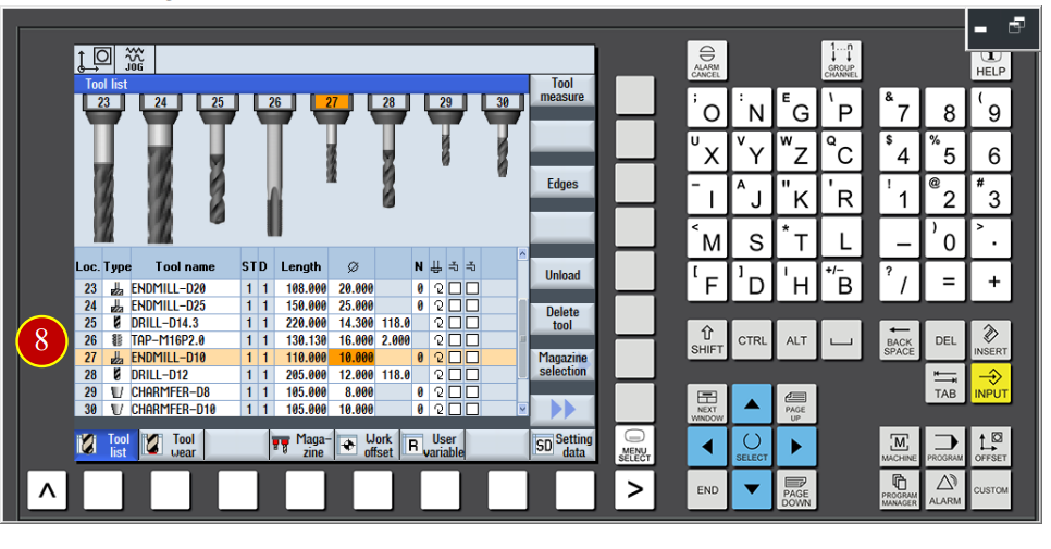
7.3 Add new tool in the controller panel
e.g. Add new tool data [ENDMILL-D10] at No.27 tool position
7.3.1 Add new tool in the controller panel
(1) Click【JOG】button in the controller panel
(2) Switch【Program Lock】to level 3, unlock tool data list protection
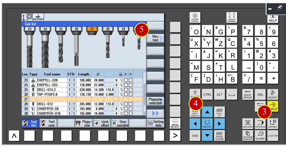
(3) Click【OFFSET】button in category function display buttons to switch to the
[Tool Data List] page
(4) Use arrow keys to move the cursor to the No.27 tool position
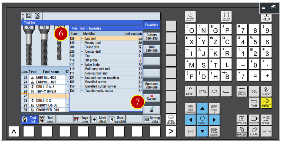
(5) Click【New Tool】option to enter the adding tool page
(6) Click【End Mill】
(7) Click【OK】to add No.27 tool
(8) Key in the basic tool data, tool name [ENDMILL-D10]
Tool Length=110mm, Diameter=10mm
7.4 Work Coordinate and Tool Offset Setting (OFFSET)
When changing a new workpiece, it needs to reset the data according to
The size of the workpiece in order to build a correct work coordinate shitf.
(X Axis, Y Axis and Z Axis). After installing the tool, setting the geomatry
Value of the tool is neccesary.
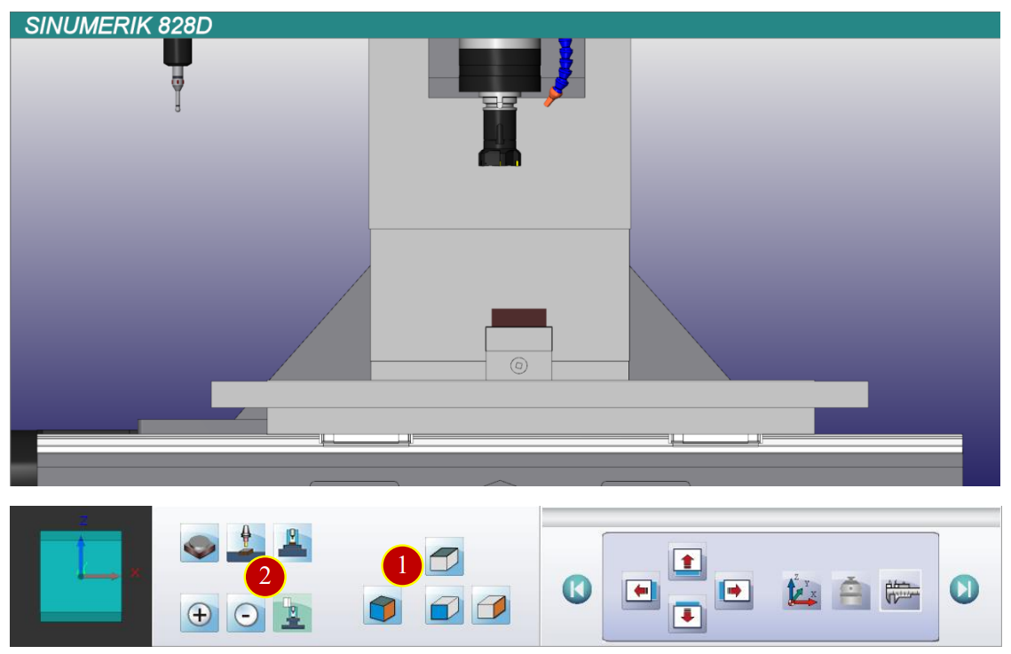
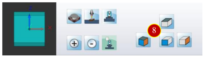
7.4.1 Adjust the view
To adjust the view to the proper offset angle and size
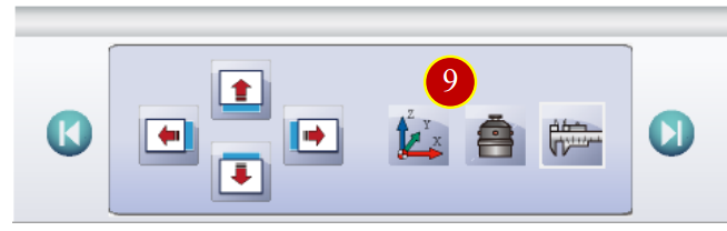
(1) Click the【Front View】button of the【View Tool Bar】
(2) Click【Shell】button to hide the shell
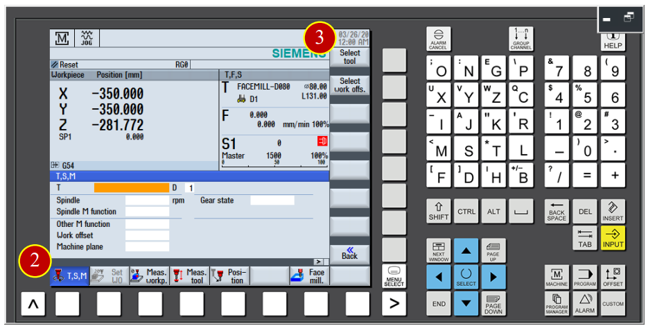
7.4.2 Change New Tool
(1) Click the【JOG】button in the controller panel
(2) Click【T,S,M】button
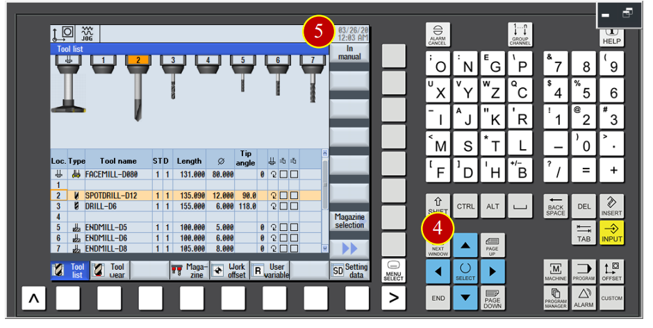
(3) Click【Select tool】function and switch to tool list window
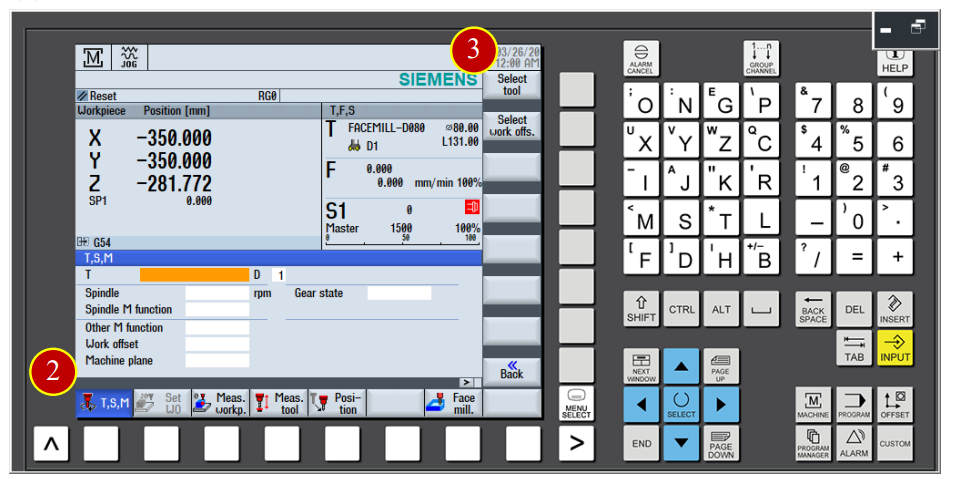
(4) Use arrow keys to move the cursor to the No.2 tool position
(5) Click【In manual】function to move the tool data to the [T,S,M] page
(6) Click the【CYCLE START】button to change the tool
(7) Before the manual operation, switch the【Feed Rate】button to 30% (or 50%)
Position (Can not be at the 100% position)
7.4.3 Work Coordinate Setting
Definition of WORK OFFSET:
(1) The shifted distance between zero point of the work and the home position of
the machine is called as Work Coordinate Offset Value (Work Coordinate Setting)
(2) Define the offset value of workpiece XY Axis through the offset action with the
[Edge Finder]
(3) When the tool magazine returns to the home position, work shift value will be seen as
an absolute coordinate of the program. Hence, machine will run the program and
do any cutting and positioning function
7.4.4 Work Z Axis meanrsurment and operation
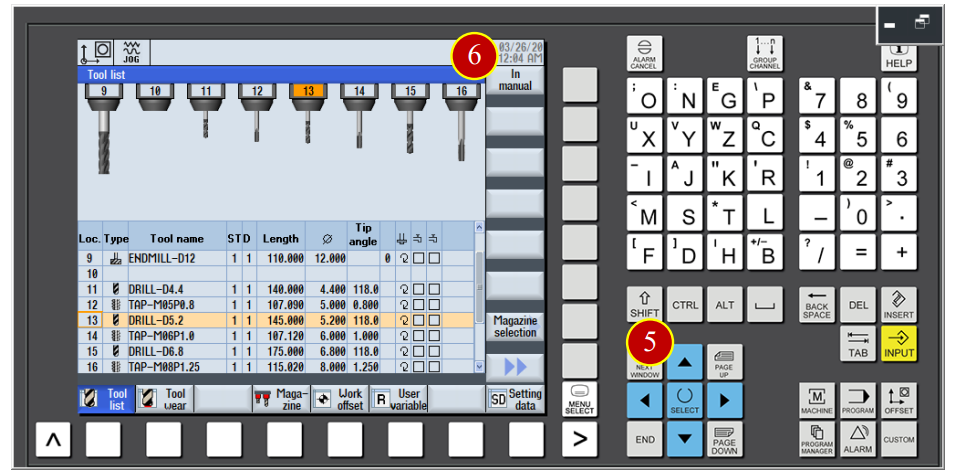
Take the no.5 tool drill (Tool Lenth=145, Diameter 5.2mm) as the example to explain the offset Method. Please check the following steps:
(1) Click the【JOG】button on the panel to switch to the [JOG] mode
(2) Click【T,S,M】function
(3) Click【Select tool】function to switch to [Tool Data List] page
(4) Switch the【Program Lock】button on the panel to level 3 to clear the tool data list
protection lock
(5) Use the arrow keys move the cursor to No.13 tool position
(6) Click【In manual】function to move to tool data list to【T,S,M】function
(7) Click the【CYCLE START】button on the panel and the machine will execute
the tool switiching movement
(8) Before manul operation, switch the【Feed Rate】button to 30% (or 50%) position
( Can not be at 100% position)
(9) Click the【Tool Setter】button to move the tool setter above the material
(10) Use the tool length setter to measure the needed position
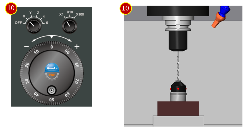
(a) Use the hand wheel and switch the hand wheel feed rate to x100
(b) Move the tool above the tool length setter untill the tool nose touch the setter, keep pushing down untill the light of the tool length setter is on.
(c) Switch the hand wheel feed rate to x10 till the light is off when the hand wheel move one scale back
(d) Rotate the hand wheel and keep pushing down, stop when the light is on
(e) Switch the hand wheel feed rate to x1 till the light is off when the hand wheel move one scale Back
(f) Rotate the hand wheel and keep pushing, stop when the light is on
(g) Adjust the hand wheel till the light is off when moving one scale back, light on when moving One scale forward.
7.4.5 Z Axis Work Coordinate Measure Setting
(1) Click【Meas. workp】button of [controller function panel]
(2) Click function button to enter the work measurement page
(3) Click【Z】Axis
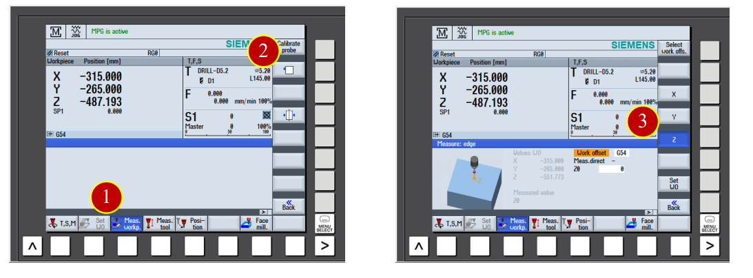
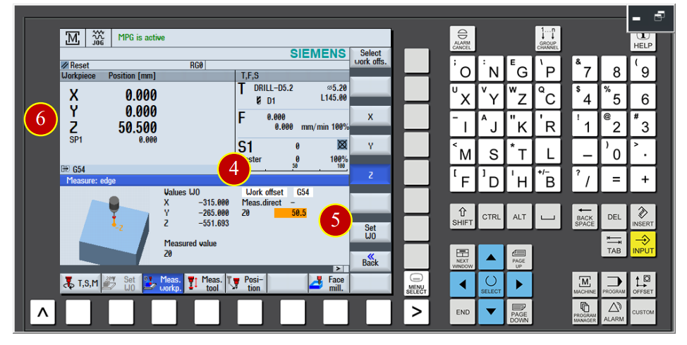
(4) Key in 50.5 in the Z0 column ( The height of tool setter is 50.0mm+ allowrance 0.5mm)
(5) Click【Zero Offset Setting】function button to execute the Z Axis measurement
(6) When the Work coordinate value show up Z= 50.5, it means the Z Axis work
coordinate shift Setting is done.
7.4.6 X Axis Work Coordinate Measure Operation
Take No.40 tool 10mm edge finder as example to explain the tool setting method Operation Steps:
(1) Click the【JOG】button to switch to the [JOG] mode
(2) Click【T,S,M】
(3) Click【Select tool】function, switch to [Tool Data List] page
(4) Use arrow keys to move cursor back to tool No.40 position
(5) Click【In manual】to move the tool back to [TSM] function
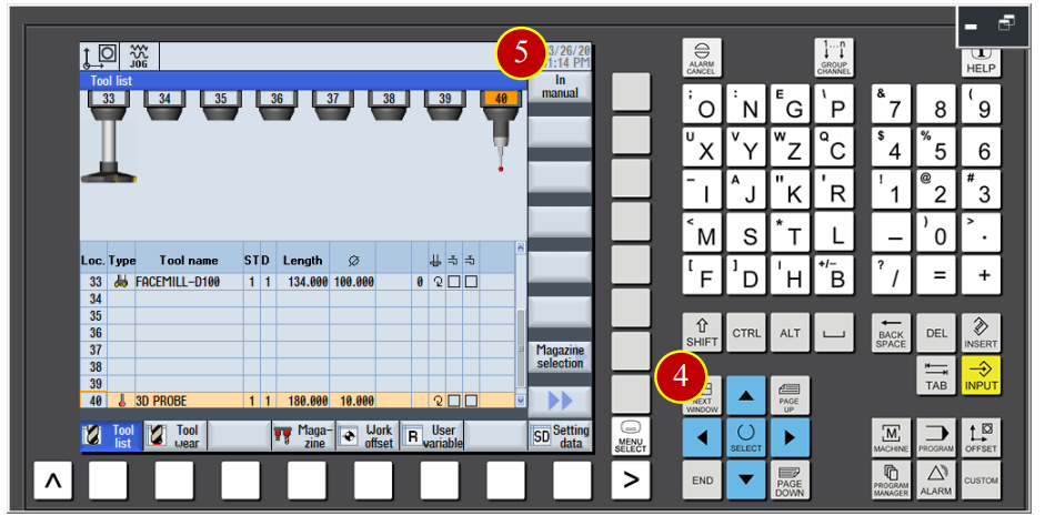
(6) Click【CYCLE START】button and machine will start execution
(7) Before manual operation, switch [Feed Rate] button to 30% (or 50%) position
(Can not be at 100% position)

(8) Click the【Front View】button of the [View Tool Bar]
(9) Click the【MPG】button on the panel to start【MPG】hand wheel
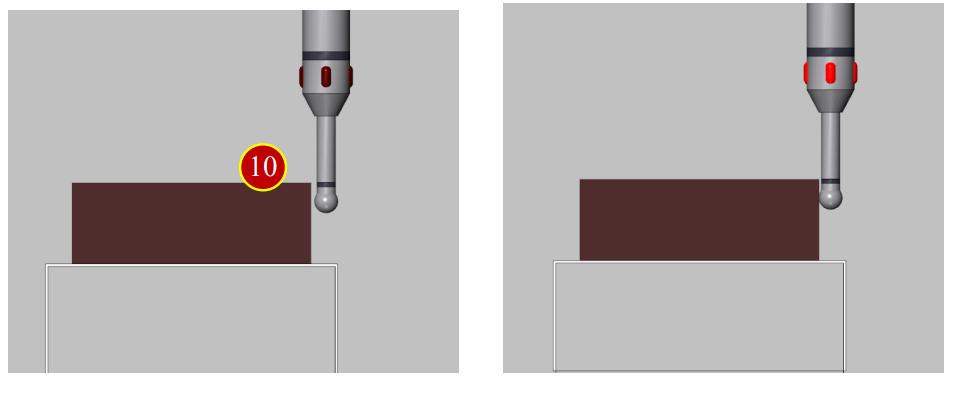
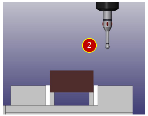
(10) Use edge finder to touch the work from the right side to measure the needed position
(a) Use the hand wheel and switch the hand wheel feed rate to x100
(b) Use the edge finder to touch the workpiece, stop when the light is on
(c) Switch the hand wheel feed rate to x10 till the light is off when the hand wheel move one scale back
(d) Move the edge finder forward to touch the workpiece, stop when the light is on
(e) Switch the hand wheel feed rate to x1 till the light is off when the hand wheel move one scale Back
(f) Move the edge finder forward to touch the workpiece again, stop when the light is on
(g) Adjust the hand wheel till the light is off when moving one scale back, light on when moving one scale forward.
7.4.7 X Axis Work Coordinate Measure Setting
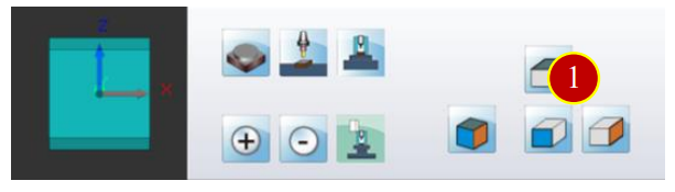
(1) Click the【Meas. workp】button of [Controller function panel]
(2) Click function button to enter the work measurement page
(3) Click【X】Axis
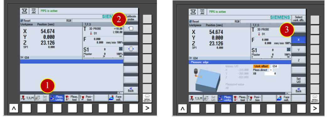
(4) Click【Select】function button at the【Meas. Dirrect】, change column value to –
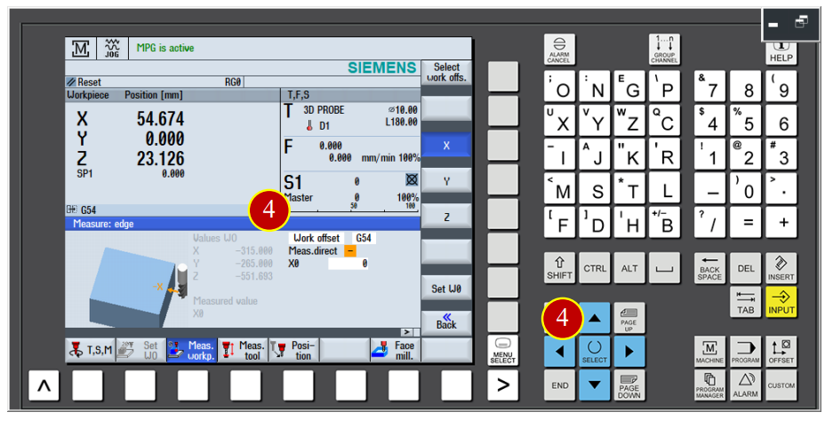
(5) Key in 50 in X0 column (50.000mm apart from material center)
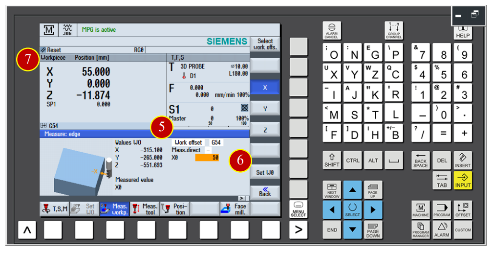
(6) Click【Zero Offset Setting】function button to execute the X Axis measurement
(7) When the Work coordinate value show up X=55.000, it means the X Axis work
coordinate shift Setting is done.
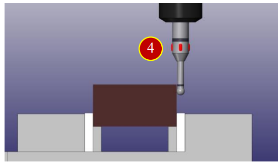
7.4.8 Y Axis Work Coordinate measure operation
(1) Click the【Side View】button of the [View Tool Bar]
(2) Use the Axial movement controller button and move the edge finder rapidly to
about 100mm apart from the workpiece
(3) Click the【MPG】button on the panel to start the【MPG】hand wheel
(4) Use the edge finder to touch the workpiece from the back side to
measure the needed position
(a) Use the hand wheel and switch the hand wheel feed rate to x100
(b) Use the edge finder to touch the workpiece, stop when the light is on
(c) Switch the hand wheel feed rate to x10 till the light is off when the hand wheel move one scale back
(d) Move the edge finder forward to touch the workpiece, stop when the light is on
(e) Switch the hand wheel feed rate to x1 till the light is off when the hand wheel move one scale Back
(f) Move the edge finder forward to touch the workpiece again, stop when the light is on
(g) Adjust the hand wheel till the light is off when moving one scale back, light on when moving One scale forward.
7.4.9 Y Axis Work Coordinate Measure Operation
(1) Click【Meas. workp】function button
(2) Click function button, enter the work measurement page
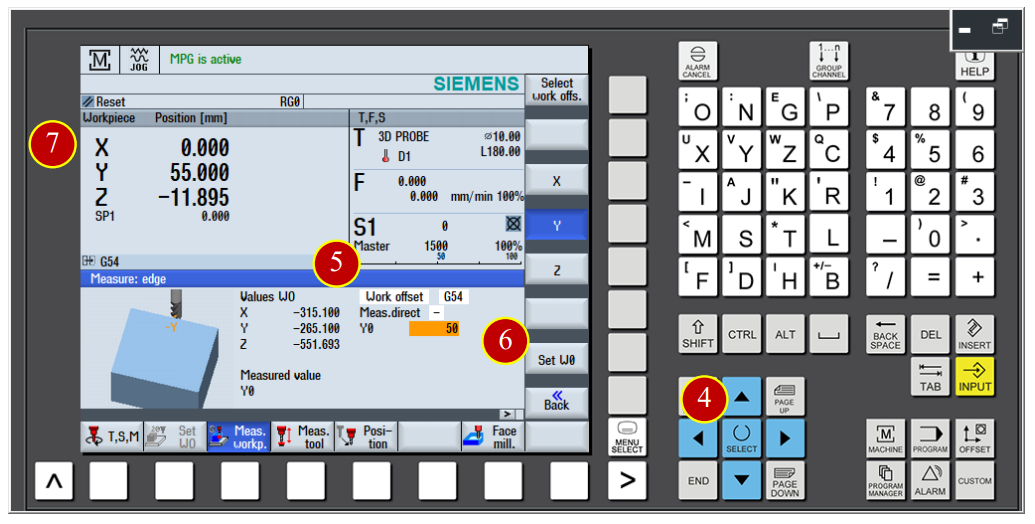
(3) Click【Y】Axis
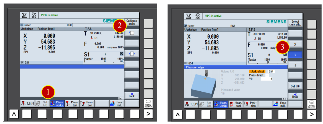
(4) Click【Select】function button of the【Measure Edge】column, change the column value to –
(5) Key in 50 in Y0 column (50.000mm apart from material center)
(6) Click the【Zero Offset Setting】function button to execute the Y Axis measurement
(7) When the Work coordinate value show up Y=55.000, it means the Y Axis work
coordinate setting is done.
7.5 Auto Run Execution
Use the auto run function to execute the CNC program with controller
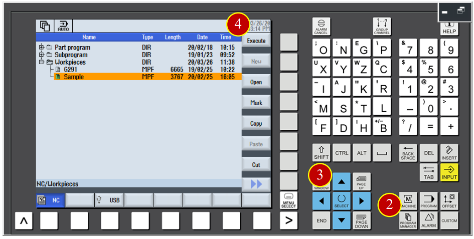
7.5.1 Select the CNC machining steps
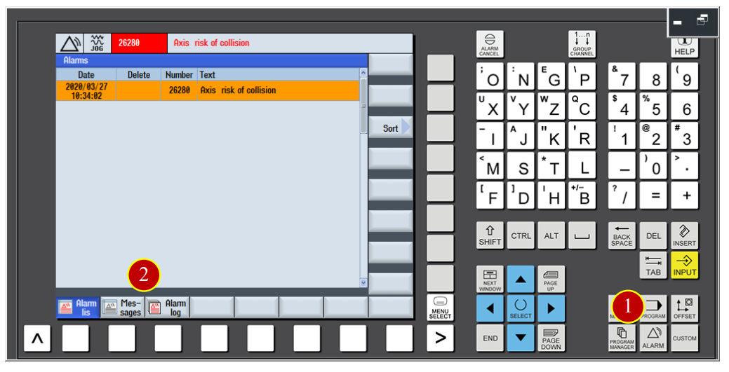
(1) Click the【AUTO】button on the controller panel, switch to [AUTO] mode
(2) Click【PROGRAM MANAGER】
(3) Use arrow keys to move the cursor to program position Sample.MPF
(4) Click【Execute】function to load in the Sample.MPF program, and switch to
the Machine machining area automaticlly
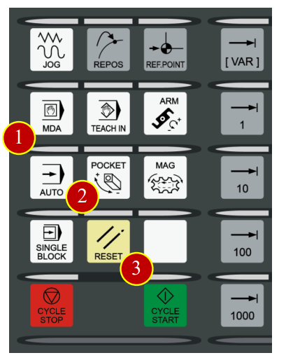
7.5.2 Check Auto Run Operation Button
(1) Before the program automatically run, switch the【Feed Rate】to [30%] position
(2) Click【FEED START】to execute the cutting feed function
(3) Click【SINGLE BLOCK】single block button, and when the light is on it means
it’s functioning
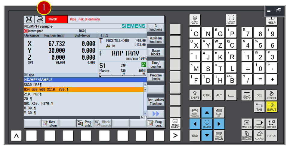
7.5.3 Program Execution
(1) Click the【CYCLE START】button in the controller panel to execute the program
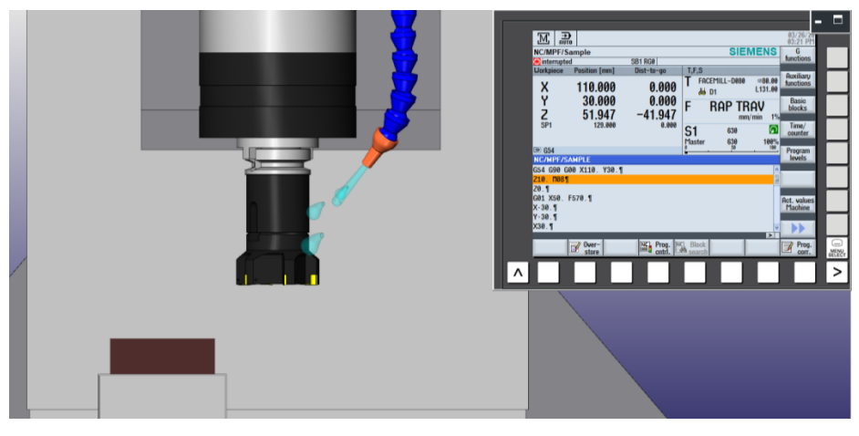
(2) Pay attention on the movement of tool, click【CYCLE STOP】button immidiately
when the tool is close to the work (about 50mm)
(3) Check if the position of tool and workpiece is match to the size of program coordinate
e.g. Program Realative Coordinate Z= 51.947, tool nose is about 50mm apart from work by vision
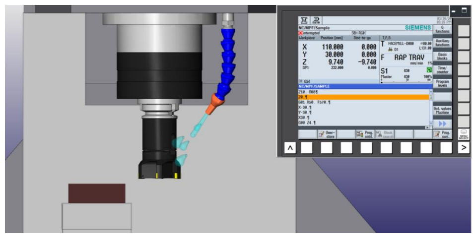
(4) Click【CYCLE START】to continue the program execution
(5) When the tool is closer to the work (about 10mm apart), click【CYCLE STOP】to
stop the feeding
(6) Switch the【Feed Rate】button to [80%] position
(7) Make sure the position of tool and work is match to the program coordinate value
(a) *Caution: During the commissioning period, as long as the tool is close to the work, make sure the [RG0] RAPID SPEED EFFECTIVE is selected in order to slow down the speed of rapid movement for the safety.
(b) Anytime when feel something is wrong, click the【CYCLE STOP】button immidiately to Recheck again.
7.6 Machine Alarm
When the operation error occurs, alarm will show up on the controller panel
7.6.1 Check and clear alarm
(1) When the controller panel is showing “ALM”
(2) Check the alarming code and content, then correct the error according to the content
(3) Press【RESET】after the correction of errors to clear the alarm
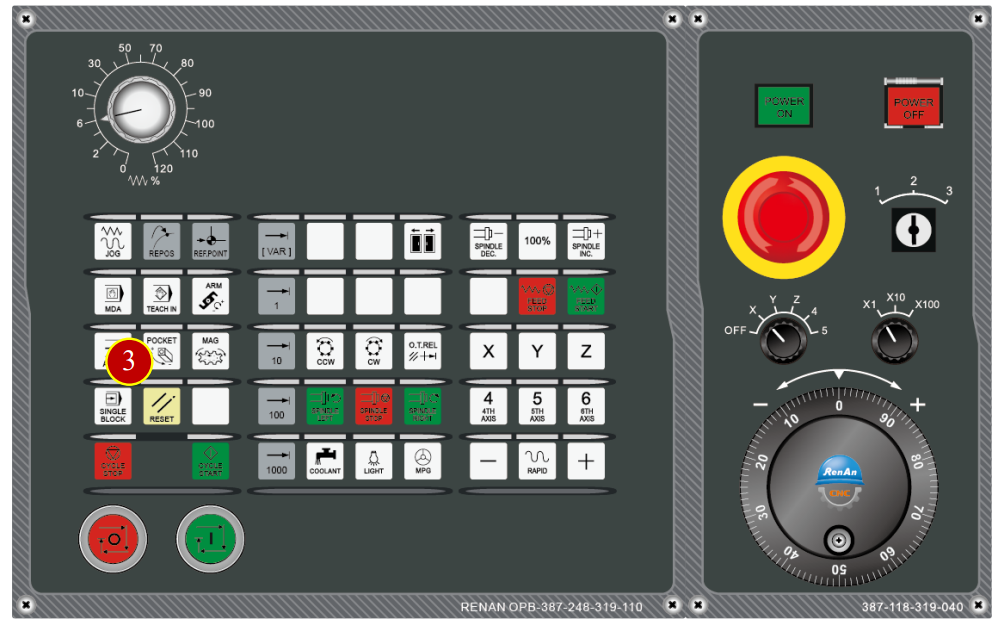
7.6.2 Check History ALARM information
(1) Press【ALARM】button
(2) Click【Alarm log】option to check the history information
7.6.3 Back to AUTO Run
When the program is interrupted, or trying to go back to AUTO Run window from the alarm notifition
(1) Press【AUTO】to return to the program display window
(2) Click【RESET】button on the panel to move the cursor backto the beginning
of the program
(3) Make sure the cursor is at the begginging and click【CYCLE START】to auto-execute
文章區塊