

CH6_Basic Machine Operation_Heidenhain Milling
today
2025-01-23
local_offer
Heidenhain Milling
visibility
1894
6. Basic Machine Operation
6.1 ZRN
6.1.1 Operation Steps
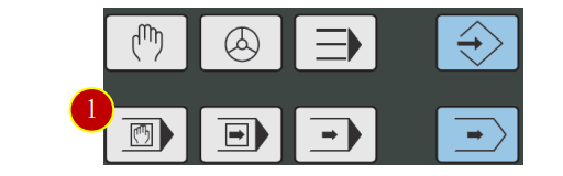
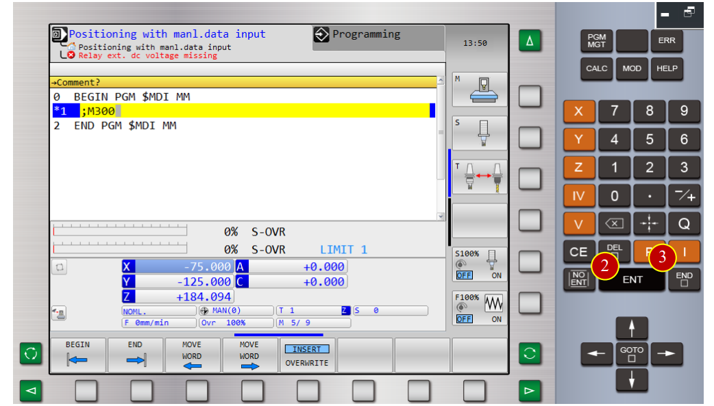
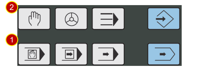
(1) Switch operation mode to [MDI] mode
(2) Key in “M300” and press [ENT]
(3) Press [END] to finish program block entry
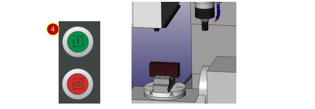
(4) Press [CYCLE START] , each axis returns to reference position
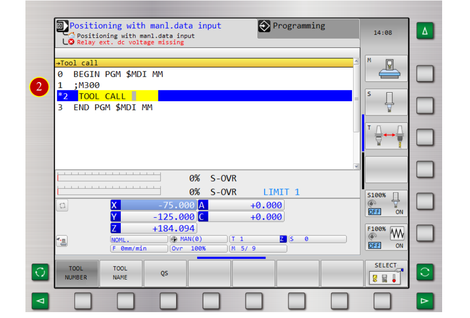
6.2 Manual Tool Change
Take tool No.3 as example to change tool manually
6.2.1 Operation Steps
(1) Switch to [MDI] mode
(2) [TOOL CALL] to insert [TOOL CALL] program block
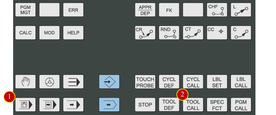
(3) Key in [ 3 ] and press [ENT]
(4) Press [NO ENT] several times until Z and horizontal soft key appear , press [AXIS Z]
(5) Press [ENT] to confirm tool axis
(6) Press [END] to finish [TOOL CALL] program block entry
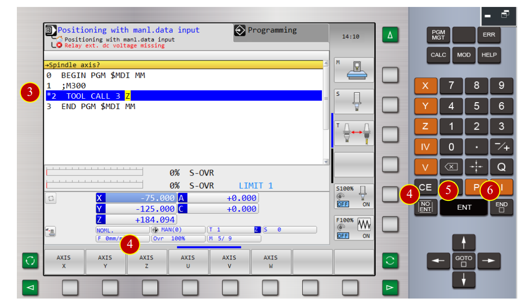
(7) Press [CYCLE START] to change too

6.3 Tool Offset
After tool installation, it is necessary to set the tool geometry offset value to execute
accurate cutting while running CNC program
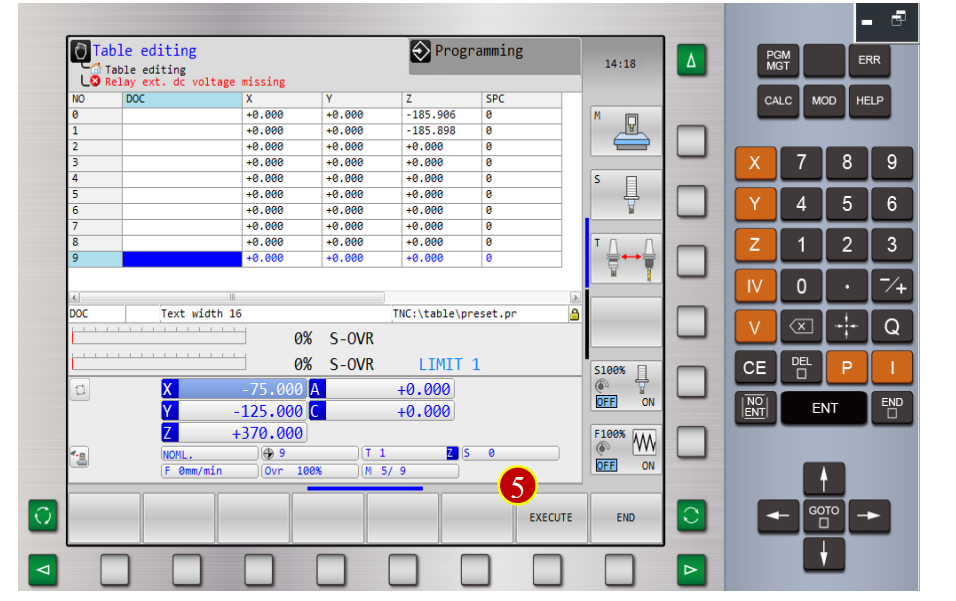
6.3.1 Work Coordinate Display and Select-(Manual Switch)
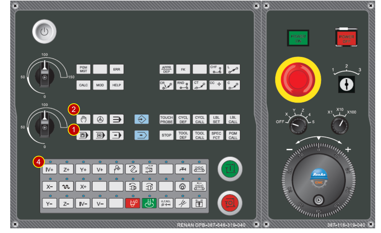
(1) Switch [Operation mode ] to [JOG mode]
(2) Press [PRESET MANAGEMENT]
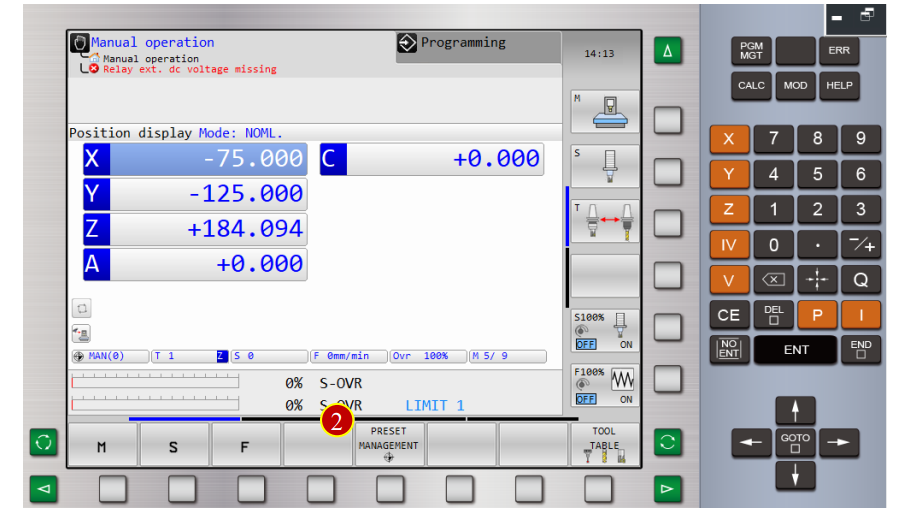
(3) Press[Direction Key] to move cursor to [No.9] coordinate
(4) Press [ACTIVATE PRESET]
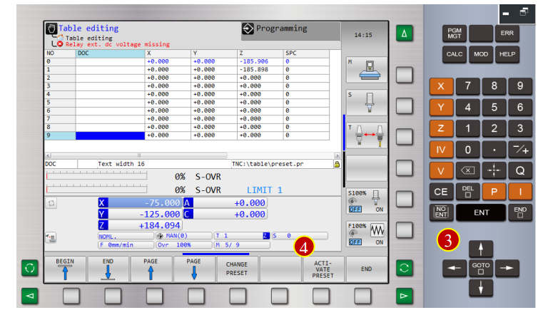
(5) [EXECUTE] to finish setup, window of [No.9] work coordinate will pop out
6.3.2 Z axis coordinate set W0
(1) Replace the spindle with an empty tool
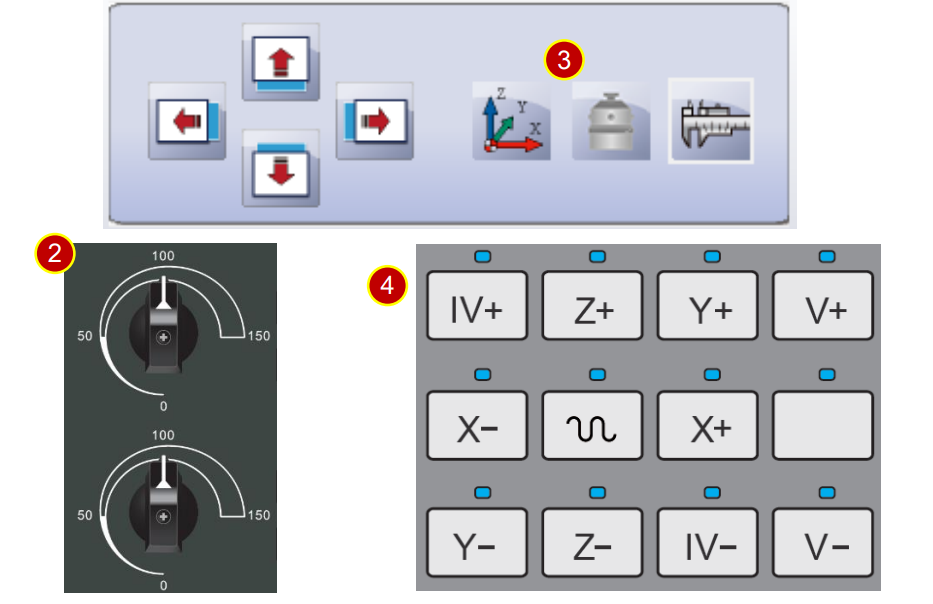
(2) Before manual operation, switch [Feed Rate ] below 50%
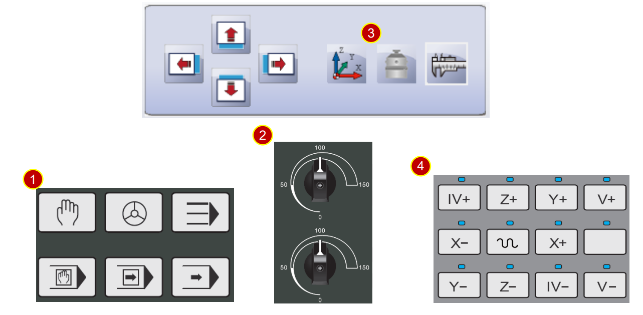
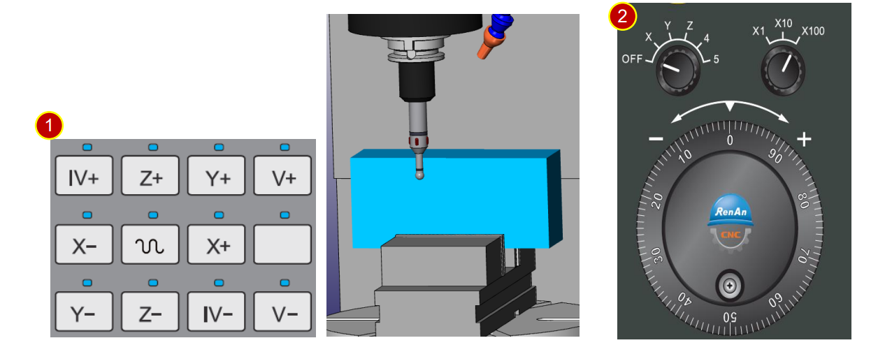
(3) Press[Application Tool Bar]> [Z Tool Setter] to place tool gauge on the material
(4) Use[ Axial Movement Buttons] to move the tool rapidly to the position , where is
about 100mm away from the workpiece
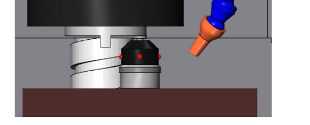
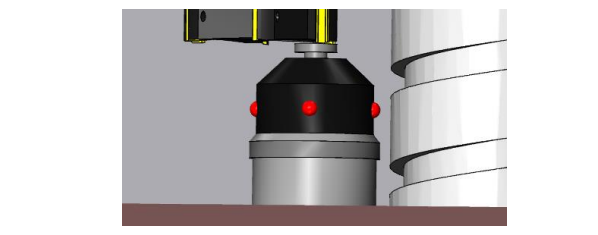
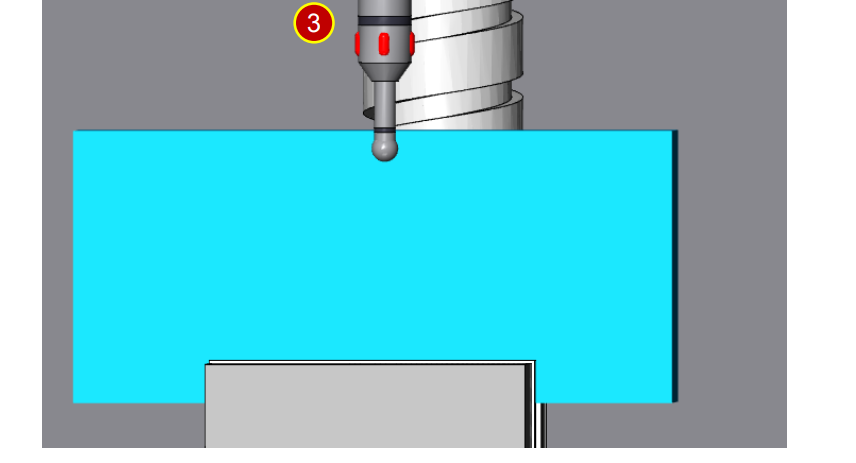
(5) Use MPG to slightly attach the spindle head to tool gauge to measure the position
(a) Switch feedrate to [x100]
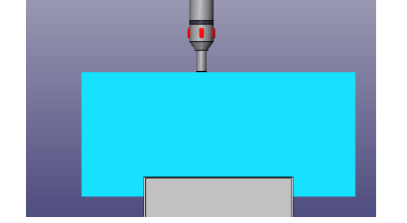
(b) Move the spindle head above the tool gauge, slightly attach the bottom of spindle
head to tool gauge. Keep executing, until tool gauge lights up and then stop
(c) When handwheel retracts one scale and light is off, adjust the feedrate to [x10]
(d) Use the handwheel to keep attaching the spindle head.
Stop, when the light is on.
(e) When handwheel retracts one scale and light is off, adjust the feedrate to [x1]
(f) Use the handwheel to keep attaching the spindle head.
Stop, when the light is off.
(g) Keep adjusting the handwheel, till the following situation, the handwheel retracts
one scale, and the light is off, or turns forward one scale, and the light is on.
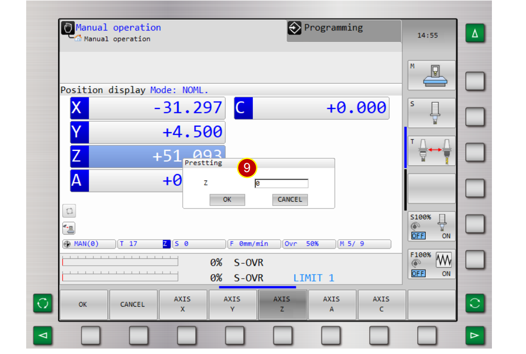
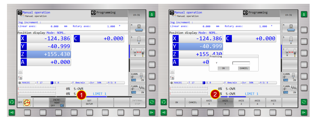
(6) [Controller Function Panel], press [ ] ,turn to page 4
(7) Press [Controller Function Panel] > [SET DATUM]
(8) Press [AXIS Z] and select Z axis
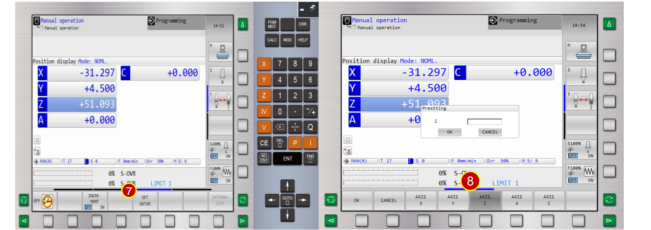
(9) Key in [ 0 ] in Z column
(10) Press [OK] to set Z axis coordinate, which is displayed as 0.000.
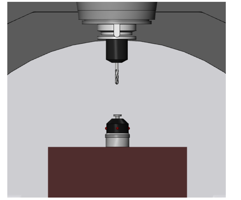
6.3.3 Measure Tool Length
Set each tool geometry offset, take Drill No.4 as example
Operation Steps:
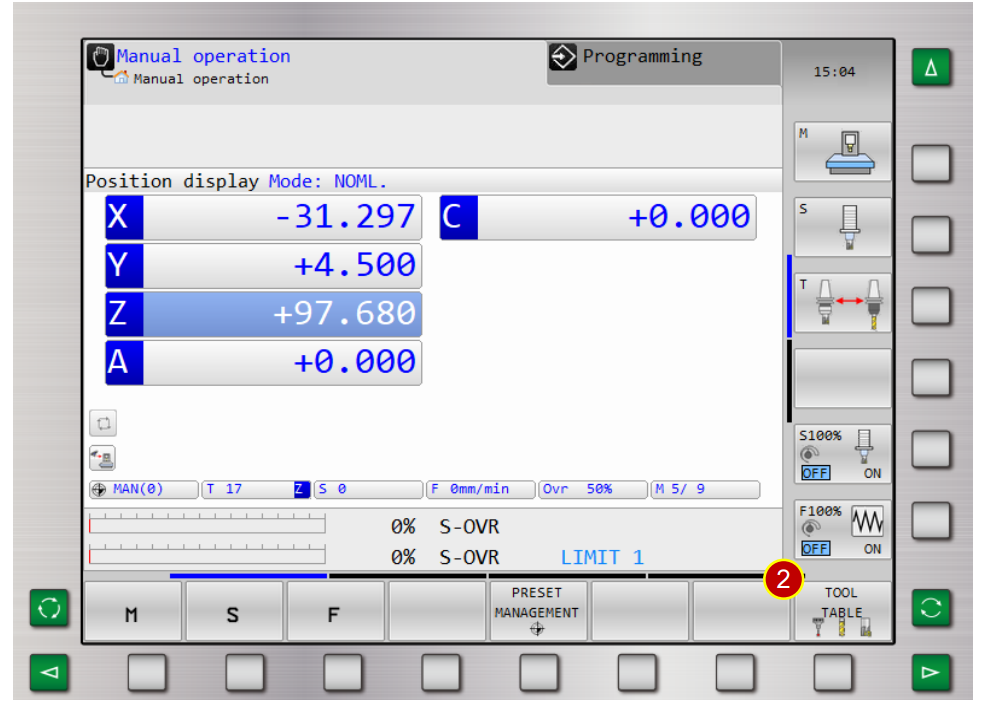
(1) Enter [MDI] interface and switch to No.4 tool
(2) Switch to [JOG] mode
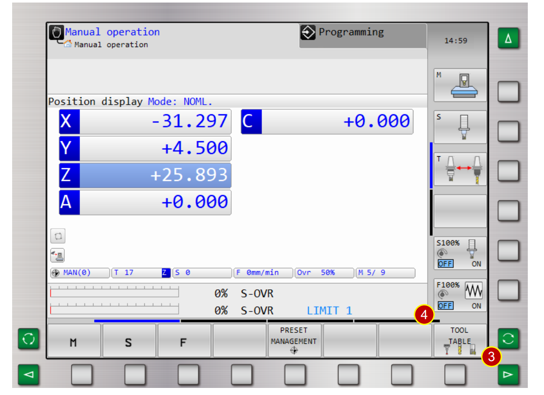
(3) Press [ ] turn to first function page
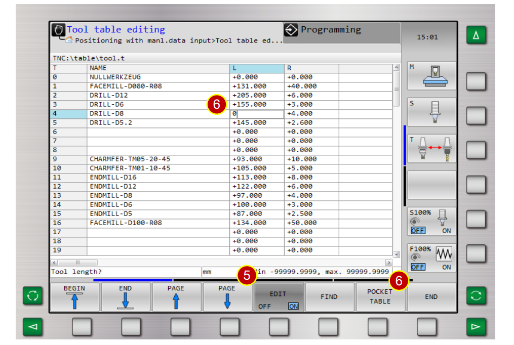
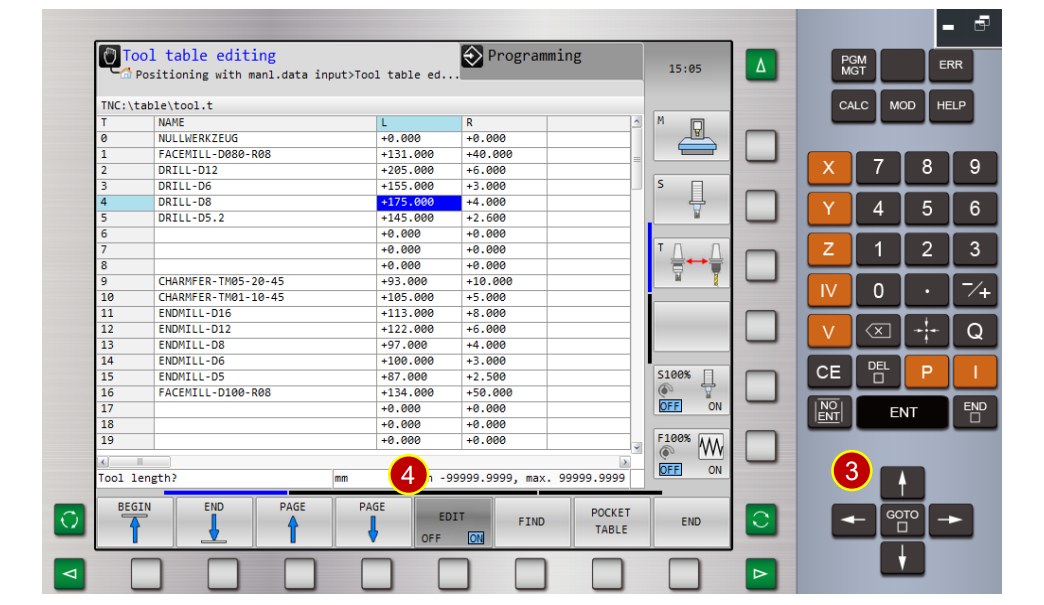
(4) Press [TOOL TABLE]
(5) Press [EDIT] to open edit status
(6) Key in [ 0] in [L column] of tool No.4 and press [END]
(7) Press [Application Tool Bar]> [Z Tool Setter]
and place tool gauge on the material
(8) Use [Axial Movement Buttons] to move the tool to the position,
where is about 100mm away from the workpiece.
(9) Switch to [MPG] mode
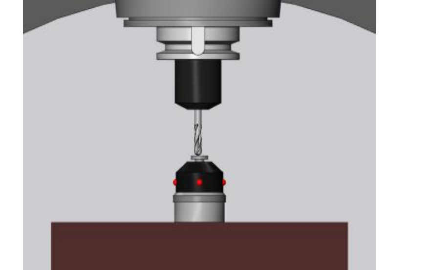
(10) Use handwheel to slightly attach the tool nose to tool gauge to measure the position
(a) Switch the handwheel feedrate to [x100]
(b) Move the tool above the tool gauge, slightly attach the tool nose to too gauge,
continue the execution till the tool gauge lights up.
(c) When handwheel retracts one scale and light is off,
adjust the handwheel feedrate to[ x10]
(d) Keep attaching the tool nose till the light is on.
(e) When handwheel retracts one scale and light is off,
adjust the handwheel feedrate to[ x1]
(f) Keep attaching the tool nose till the light is on.
(g) Keep adjusting the handwheel, till the following situation,
the handwheel retracts one scale, and the light is off,
or turns forward one scale, and the light is on.
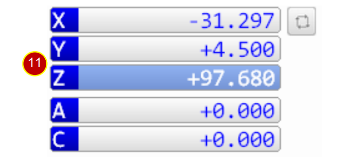
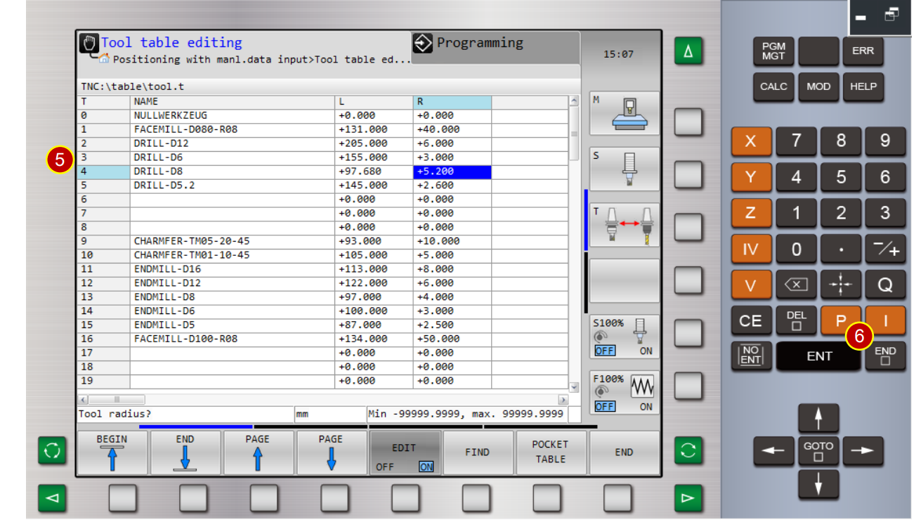
(11) Coordinate displays Z axis= +97.680,which is the tool length
6.3.4 Key in Tool Geometry Offset
Set tool geometry offset, Tool No.4 (Drill)
(tool length L=97.680 mm, radius R=5.2 mm)
Operation Steps:
(1) Switch to [JOG] mode
(2) Press [Tool Table]
(3) Press [Direction Key] to move the cursor to tool No.4
(4) Press [Edit] to turn on edit status
(5) Key in tool data
(Drill name =Drill-D8,Length L=97.680mm,Radius R=5.2mm)。
(6) Press [End]
(7) Unknown length tool , please refer to 6.3.3 and 6.3.4
or base on tool length measurement
6.4 Work Coordinate Setting
When changing to the new workpiece, it is necessary to reset the correct work
coordinate system (X axis and Z axis) according to workpiece dimensions to execute
precise cutting, while running CNC program.
6.4.1 WORK OFFSET Definition
(1) The Shift distance between the zero point of work and the home position of machine is
the work coordinate offset value.
(Work coordinate setting)
(2) Define XY axis shift value by the [Edge Finder]
(3) When turret is back to home position, the work shift value will be indicated as an
absolute coordinate of the program. Hence, machine will execute all kinds of cutting
according to the shift value.
6.4.2 Work Coordinate Setting (Z Axis)
(1) Switch to [JOG] mode
(2) Before manual operation ,switch[Feedrate] to 25%
(3) Press[View Tool bar] > [Z Tool Gauge] to place tool gauge on the material
(4) Use [Axial Movement Buttons] to move the tool to the position, where is about
100mm from the workpiece
(5) Use handwheel, slightly attach the tool nose to tool gauge to measure the position
(a) Switch the handwheel feedrate to [x100]
(b) Move the tool above the tool gauge, slightly attach the tool nose to too gauge,
continue the execution till the tool gauge lights up.
(c) When handwheel retracts one scale and light is off,
adjust the handwheel feedrate to[ x10]
(d) Keep attaching the tool nose till the light is on.
(e) When handwheel retracts one scale and light is off,
adjust the handwheel feedrate to[ x1]
(f) Keep attaching the tool nose till the light is on.
(g) Keep adjusting the handwheel, till the following situation,
the handwheel retracts one scale, and the light is off,
or turns forward one scale, and the light is on.
(6) Press [ ] to turn to the last page
(7) Press[Controller Function Panel] > [SET DATUM]
(8) Press [AXIS Z]
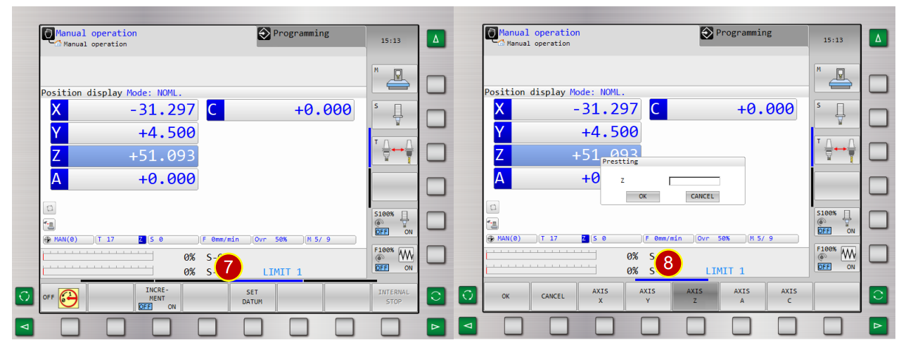
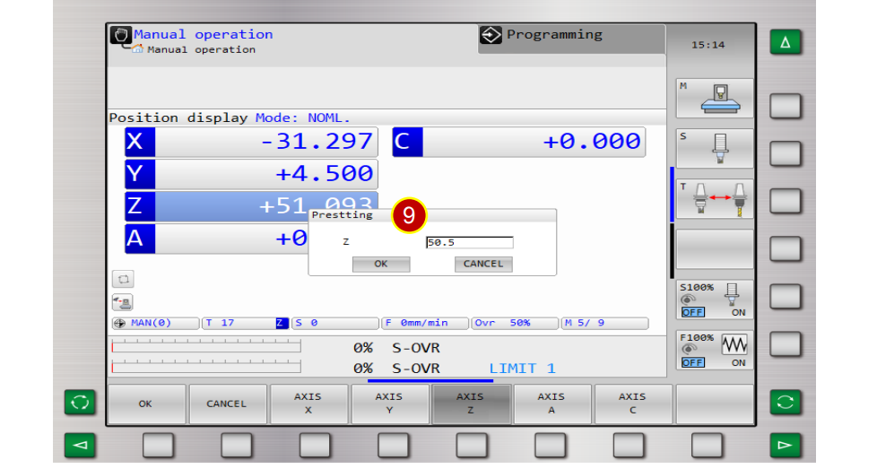
(9) Key in [50.5] in Z column
Height of the tool gauge=50.000mm + machining allowance= 0.5mm)
(10) Press [OK] to execute the calculation, Z axis displays[ +50.500],
it means Z Axis coordinate setting is done.
6.4.3 Find Edge (X axis)
(1) Enter [MDI] interface and switch to tool No.40
(2) Switch to [JOG] mode
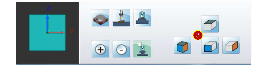
(3) Press [View Function Button] > [Front View]
(4) Use [Axial Movement Buttons] to move the edge finder rapidly to the position,
where is about 100mm from the workpiece
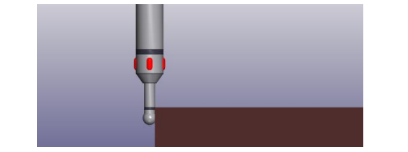
(5) Attach the edge finder to the workpiece on the right side to measure the position
(a) Use handwheel, adjust the handwheel feedrate to [x100]
(b) Attach the edge finder to the workpiece. Stop, when the light is on.
(c) When the handwheel retracts one scale, and the light is off,
adjust the handwheel feedrate to [x10]
(d) Attach the edge finder to the workpiece again; stop when the light is on.
(e) When the handwheel retracts one scale, and the light is off,
adjust the handwheel to x1
(f) Attach the edge finder to the workpiece again; stop when the light is off.
(g) Keep adjusting the handwheel, until the following situation,
the handwheel retracts one scale, and the light is off, or turns forward one scale,
and the light is on.

6.4.4 Work Coordinate Setting (X axis)
(1) Press[Controller Function Panel] > [SET DATUM]
(2) Press [AXIS X]
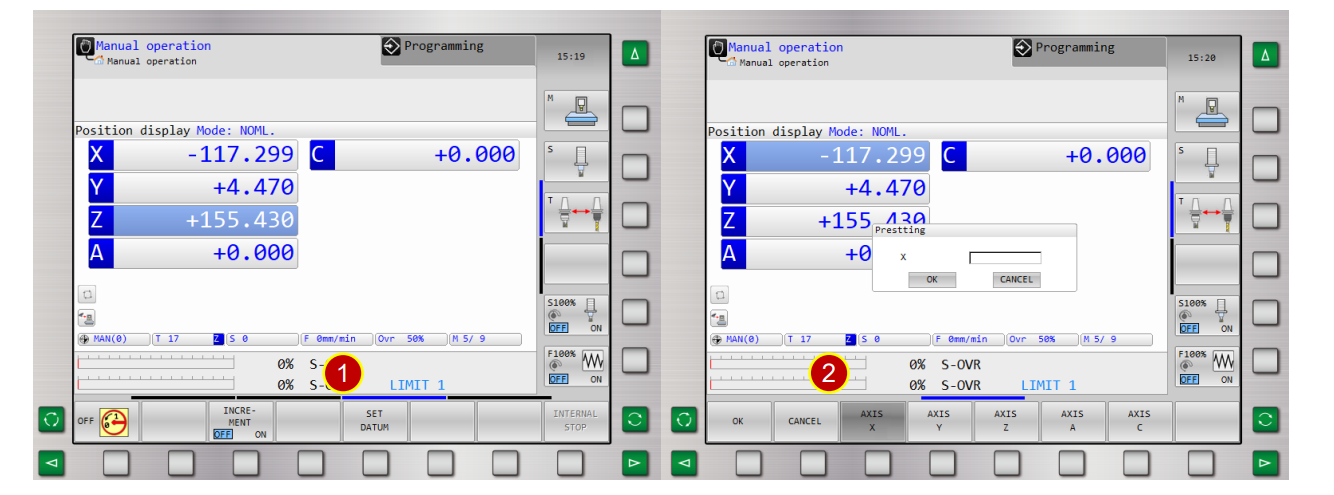
(3) Key in[ 0] in X column, press [OK] to set W0 coordinate,
the measurement of the right-sided position is done.
(4) Attach the edge finder to the workpiece on the left side to measure the position,
which displays [X=-234.579]
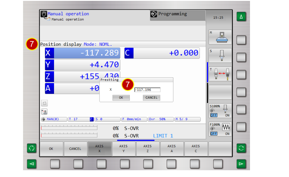
(5) Press [SET DATUM]
(6) Press [AXIS X]
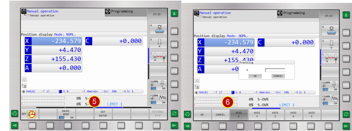
(7) Key in [-117.196] in X column and press [OK]
(X axis coordinate= -234.579/2=-117.196)
when it displays [-117.196] , then the setting is done.
6.4.5 Find Edge (Y axis)
(1) Use [Axial Movement Buttons] to move the edge finder to the position, where is
about 100mm from workpiece
(2) Select [Y] axis, rotate handwheel to move in positive direction
(3) Attach edge finder to the workpiece at the front to measure the position
6.4.6 Work Coordinate Setting (Y Axis)
(1) Press [Controller Function Panel] > [SET DATUM]
(2) Press [AXIS Y]
(3) Key in [0] in Y column, press [OK] to set W0 coordinate,
the measurement of the front position is done.
(4) Attach the edge finder to the workpiece from behind to measure the position ,
position displays [Y= +81.996]
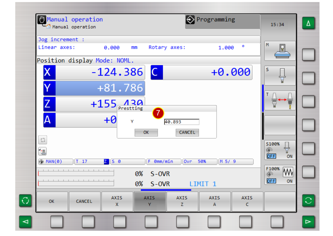
(5) Press [SET DATUM]
(6) Press [AXIS Y]
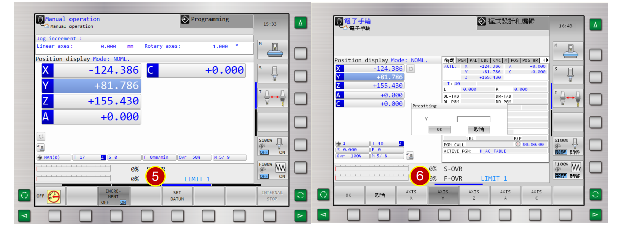
(7) Key in [ 40.893] in Y column and press [OK] (Y axis coordinate= 81.997/2=40.893)
when it displays [ 40.893] , the setting is done.
6.5 Auto-Run
Use Auto-Run to execute the CNC Program
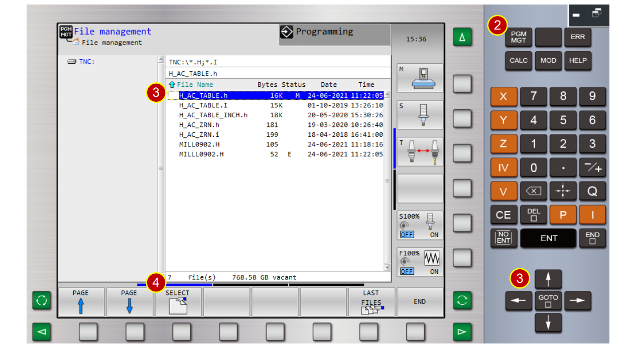
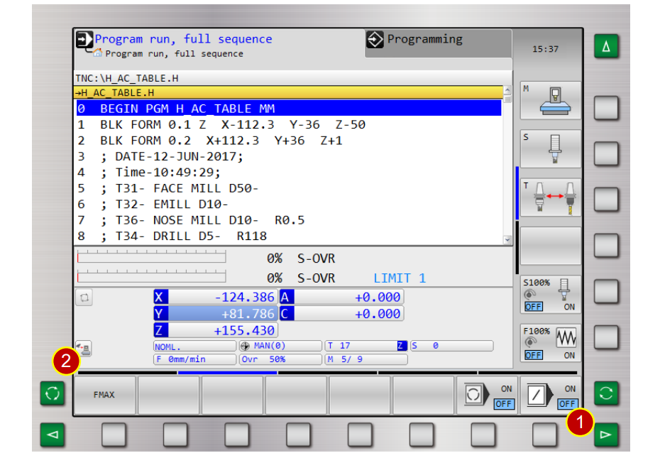
6.5.1 Select Program
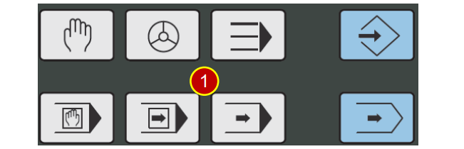
(1) Switch to [AUTO] Mode
(2) Press [PROGRAM MANAGER] 。
(3) Press[Direction Key] to move cursor to program[ H_AC_TABLE.H ]
(4) Press [Select] to input H_AC_TABLE.H program
6.5.2 Setting Before Auto-Run
Before [Auto-Run], must decrease [F MAX] value.
(1) [Controller Panel Function], press [ ] to turn to page 2.
(2) Press [F MAX]
(3) Key in [5000] and press [OK]
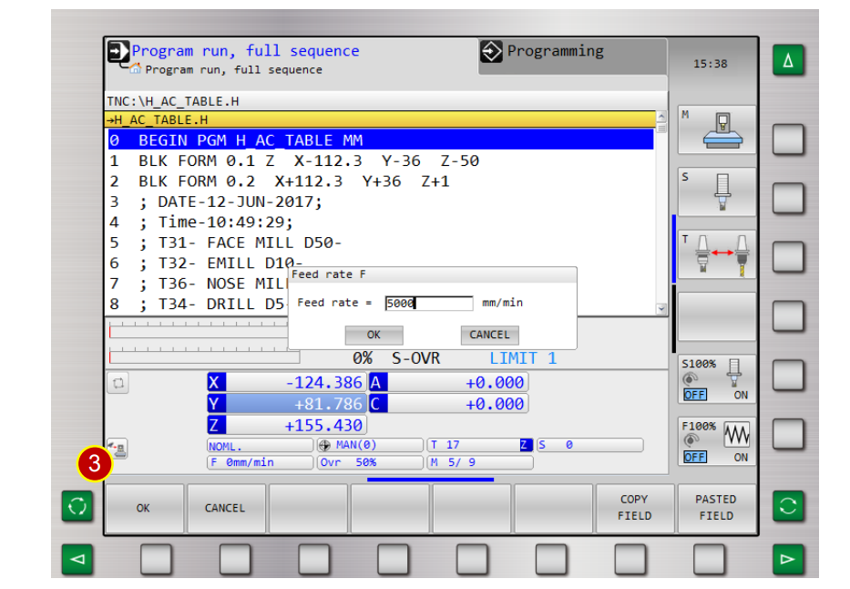
(4) Switch to [SINGLE BLOCK]
6.5.3 Run Program
(1) Press [CYCLE START] to start the program
(2) Check if the tool and workpiece are positioned accurately as per work coordinate
e.g. Program Absolute Coordinate Z= 50,
about 50mm from tool nose to workpiece by sight.
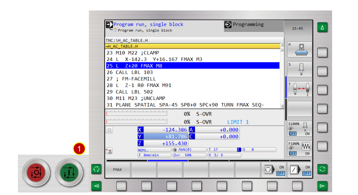
(3) Watch the tool move, when tool moves closer to workpiece(about 50mm)
press [CYCLE STOP] immediately to pause the feed
(4) Check if the tool and workpiece are positioned accurately as per work coordinate
e.g. Program Absolute Coordinate Z= 61.726,
about 60mm from tool nose to workpiece by sight
(5) Press [CYCLE START] to continue
(6) When tool moves closer to workpiece (about 10mm), press [CYCLE STOP] to stop
(7) Set [ F MAX] value as [1000]
(8) Check the tool and workpiece are positioned accurately as per work coordinate.
Caution:
(a) During trial cutting, as long as the machining is within the approaching range of the
tool and workpiece, keep [F MAX] value as [1000]
(b) Press [FEED HOLD] immediately, whenever find glitches during operation.
Cross check to ensure the correctness
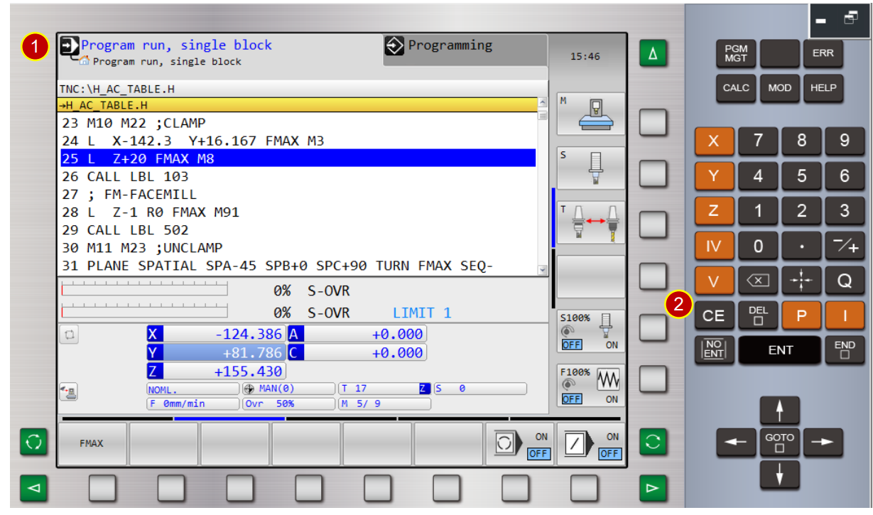
6.6 Clear Machine Alarm
When error occurs, ALARM will be displayed on the controller panel.
6.6.1 Operation steps
(1) When the controller panel displays [ALM ]. Check alarm code and content and deal
with it based on the content
(2) After getting the message, press [CE] to clear ALM
文章區塊