
CH5_Program Calculation
today
2026-08-27
local_offer
CNC, CADCAM
visibility
90
5. Program Calculation
5.1 Lathe Intersection Calculation
Using a guided graphical interface, the system automatically calculates the related
coordinate data based on the dimensions provided in the drawing. After selecting the tool
and cutting direction, a CNC program with tool radius compensation is generated. The lathe
circular arc intersection calculation program is highly efficient.
5.1.1 Open Lathe Expert
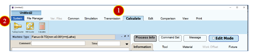
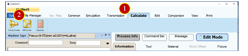
(1) Switch the function tab to 【 Ca lculat e 】
(2) Click 【 Turning Counter 】 to enter the 【 Lathe Intersection Calculation 】 main window.
5.1.2 Select Processing Type
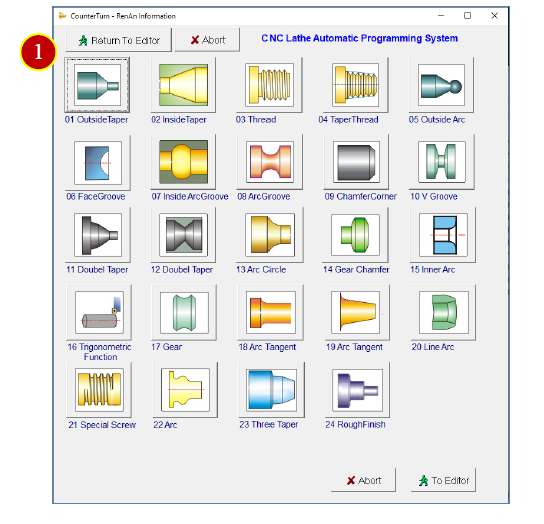
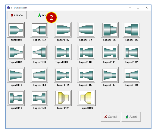
The lathe intersection calculation offers various processing types to choose from.
(1) Graphic Type
Example: Click 【 01 Out sider Taper 】 to enter the 【 Detailed Graphics 】 window for the
outer diameter taper.
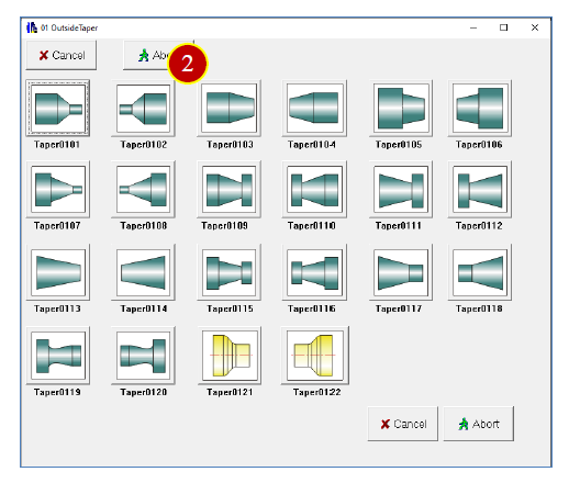
(2) Select the graphic to be processed
Example: Click 【 Taper 0103 】 to enter the 【 Intersection Calculation 】 window.
Note: Based on the selected graphic type, various detailed graphics representing that
type will be displayed.
5.1.3 Enter Machinin g Conditions
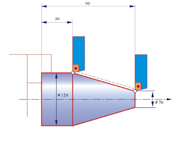
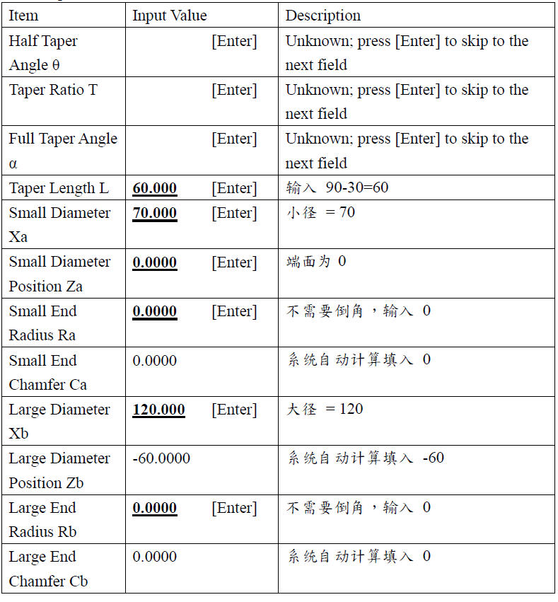
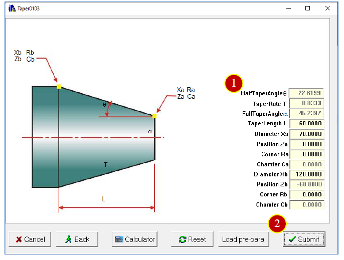
(1) Enter the dimensional specifications from the drawing. The system will automatically
calculate any missing values based on the input.
Enter critical dimensions first; skip less important or unknown ones. Input the relevant
dimensions from the drawing in sequence.
Example:
(2) Click 【 Submit 】 to enter the 【 Tool Selection 】 window.
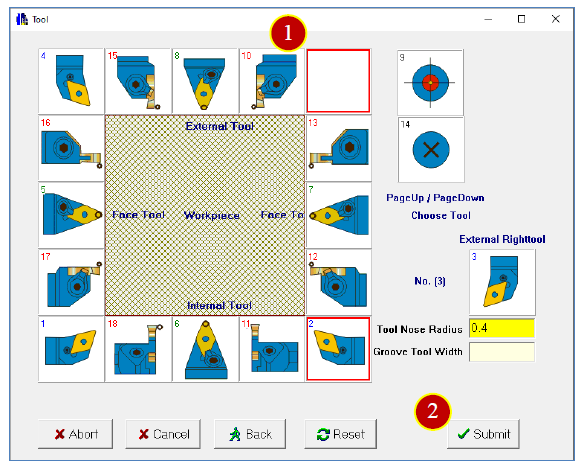
5.1.4 Select Tool and Cutting Direction
(1) Select an appropriate tool.
Example: Outer diameter right hand tool, Tool nose radius = 0.4
(2) Click 【 Submit 】 to enter the 【 Direction Selection 】 window.
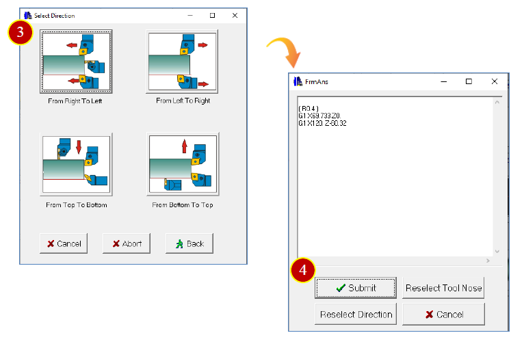
(3) Select the cutting direction.
Example: Click 【 From Right to Left 】
(4) After completion, you can preview the result.
Click 【 Submit 】 to return to the 【 Lathe Intersection Calculation 】 main window.
5.1.5 Import Result Back to Editor
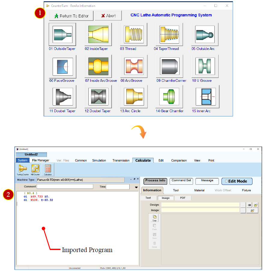
(1) Click 【 Return to Edit or 】 to go back to the 【 Edit 】 window
(2) The system will automatically import the program into the editor
5.2 Milling Intersection Calculation
Using a guided graphical interface, the system automatically calculates relevant coordinate
data based on the input drawing dimensions. After entering the milling parameters, the
CNC milling program is generated automatically.
5.2.1 Launch Milling Expert
(1) Switch the function tab to 【 Calculat e 】
(2) Click 【 Mill Counter 】 to enter the 【 Milling Intersection Calculation 】 main window
5.2.2 Select Machining Type
The Milling
Intersection Calculation provides options such as circular hole patterns and
linear drilling/tapping types.
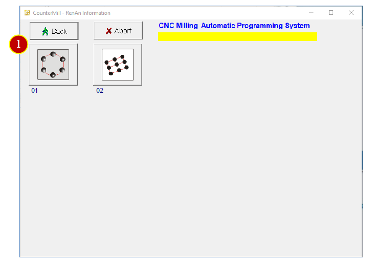
(1) Graphic type,
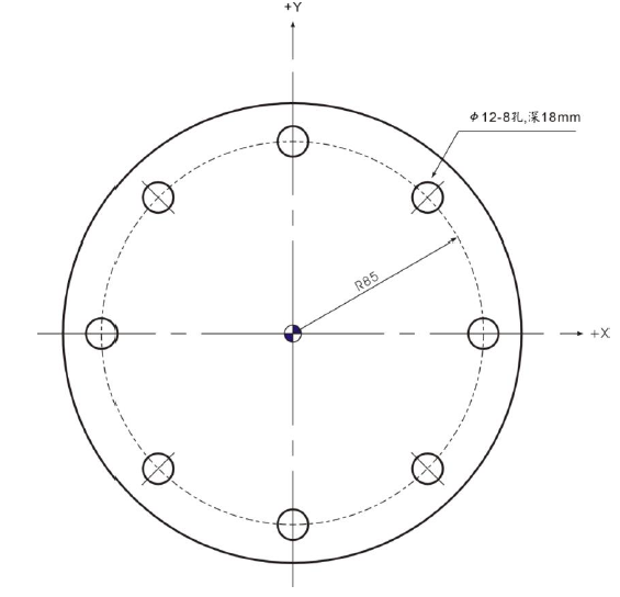
Example: Click 【 01 Circular Hole Drilling/Tapping 】 to enter the 【 Detailed Graphic 】
window for circular hole drilling/tapping.
(2) Select the graphic to be processed,
Example: Click 【 Circular Hole N=8 】 to enter the 【 Intersection Calculation 】 window.

5.2.3 Enter Machining Conditions
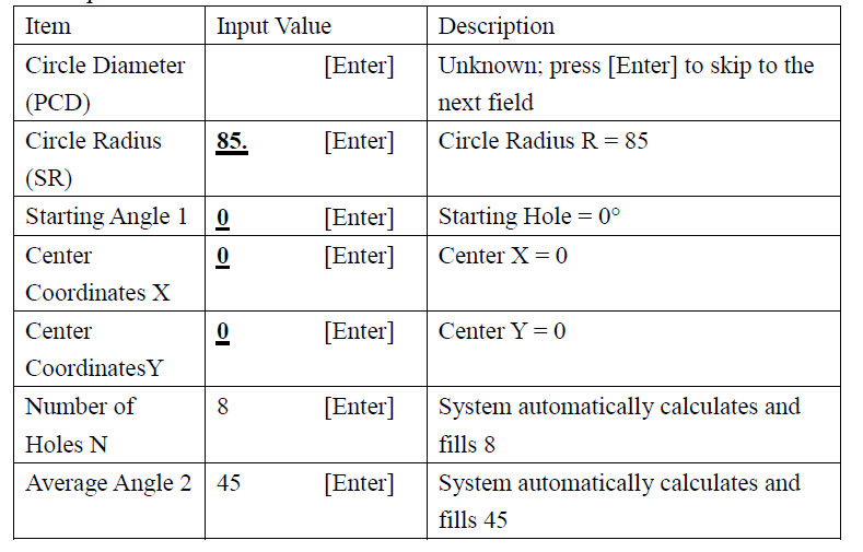
(1) Enter the dimensional specifications from the drawing. The system will automatically
calculate any miss ing values based on the input.
Enter critical dimensions first; skip less important or unknown ones. Input the relevant
dimensions from the drawing in sequence.
Example:
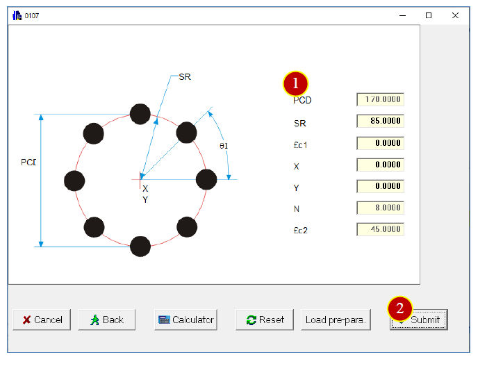
(2) Click 【 Submit 】 to enter the 【 Loop Command 】 selection window.
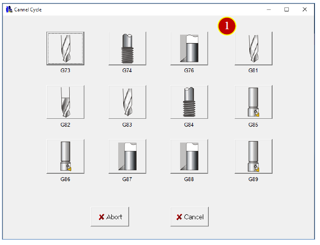
5.2.4 Select Drilling and Boring Cycle
(1) Choose the drilling and boring cycle type,
Example: Click 【 G81 Drilling Cycle 】 to enter the 【 Tool Parameters 】 window.
5.2.5 Enter Milling Parameters
(1) Enter tool parameters,
Example:
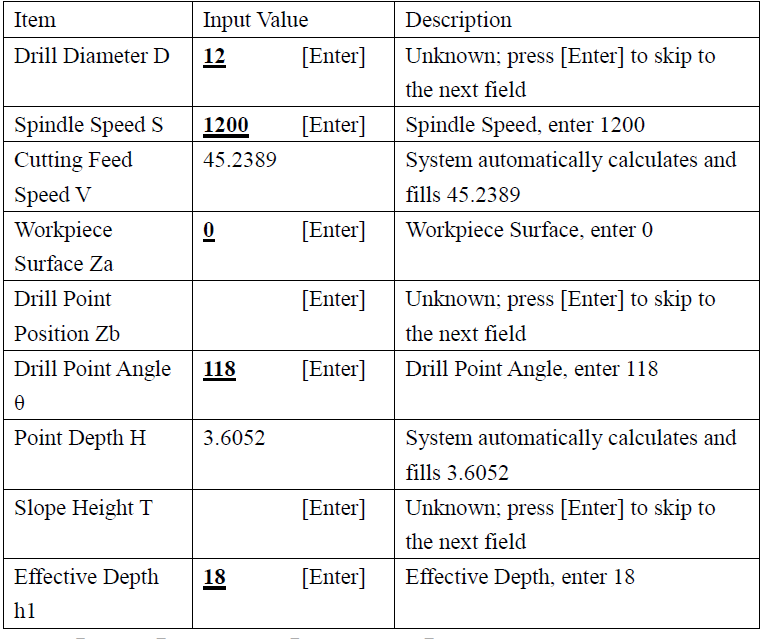
(2) Click 【 Submit 】 to enter the 【 Feed Control 】 window.
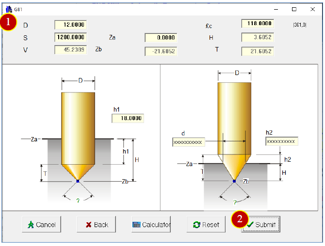
(3) Enter feed control parameters,
Example: Starting Point Position Zs = 50
R Point Position ZR = 5
Feed Rate per Minute F = 120
Select 【 G90 Absolute Positioning 】
Select 【 G99 Tool Return to R Point 】
(4) Click 【 Submit 】 to preview the result,
(5) Click 【 Submit 】 to return to the 【 Milling Intersection Calculation 】 main window.
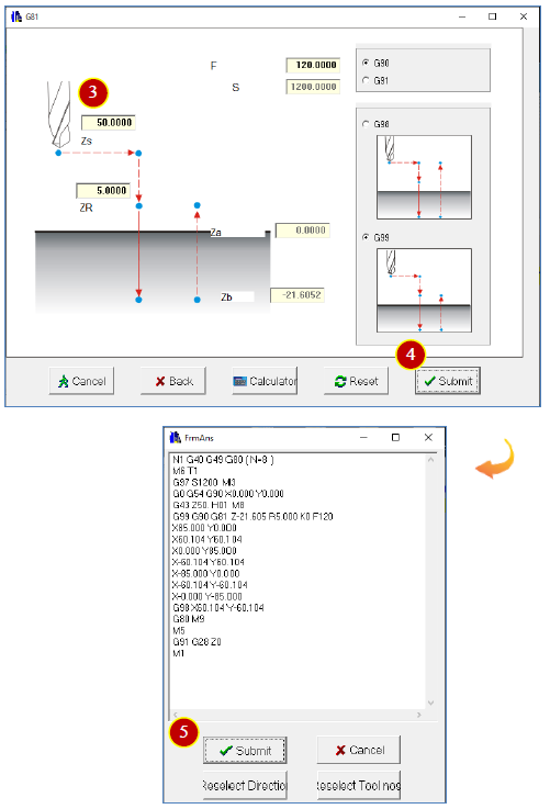
5.2.6 Import Result Back to Editor
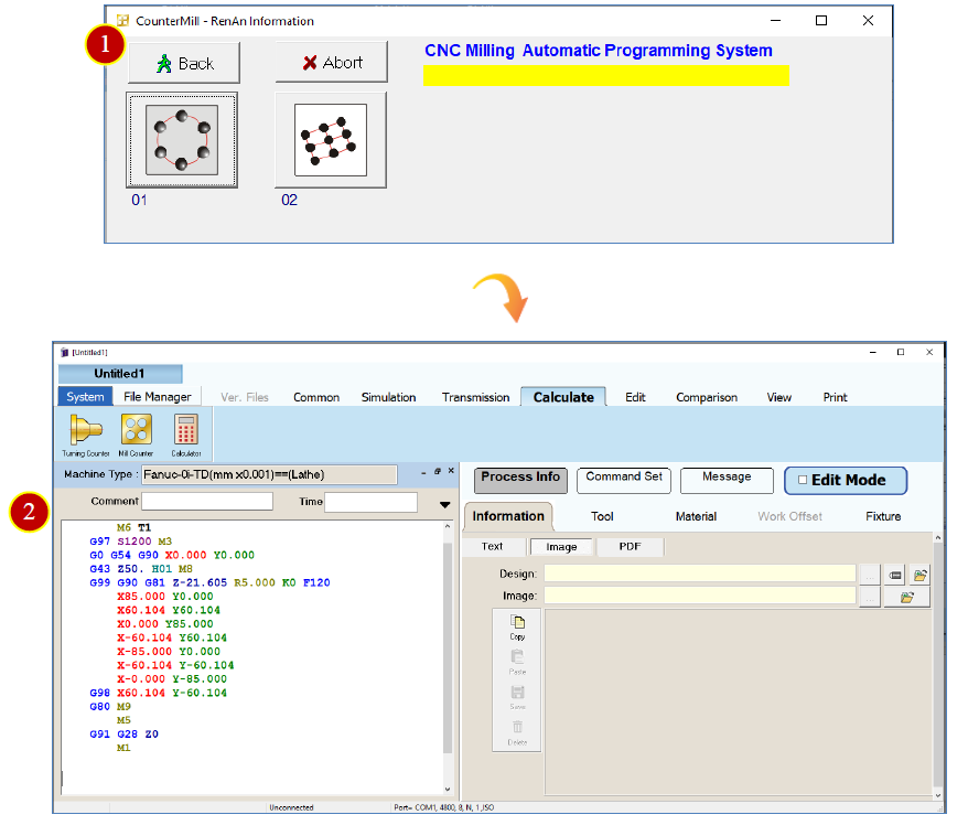
(1) Click 【 Back 】 to go back to the 【 Edit 】 window.
(2) The system will automatically import the program into the editor.
文章區塊